Flomega, liquid mfc’s/mfm’s – Brooks Instrument 5882/92 User Manual
Page 16
16
Installation and Operation Manual
X-TMF-FM-MFC-eng
PN 541-C-007-AAG
April, 2008
Flomega, Liquid MFC’s/MFM’s
FLOMEGA
A new thermal measurement principle is used in our Flomega. The patented thru-flow sensor is especially
designed for liquids and is different from the traditional Brooks 5850 series “thermal” mass flow meters for
gases.
The by-pass or shunt technique used for gases cannot be applied for liquids; viscosity variations, air
bubbles, convection and attitude sensitivity deteriorates the performances dramatically. Therefore, Brooks
Instrument developed Flomega. This thru-flow meter is unique in its patented design, performance and
reliability.
In the new sensor, the heat transfer to and from the liquid is perpendicular to the pipe axis contrary to
classic way of heat transfer along the pipe wall. This technique enables a high heat current to and from
the liquid, which is essential for a thru-flow sensor. Using thermal feedback reduces power consumption
to a minimum.
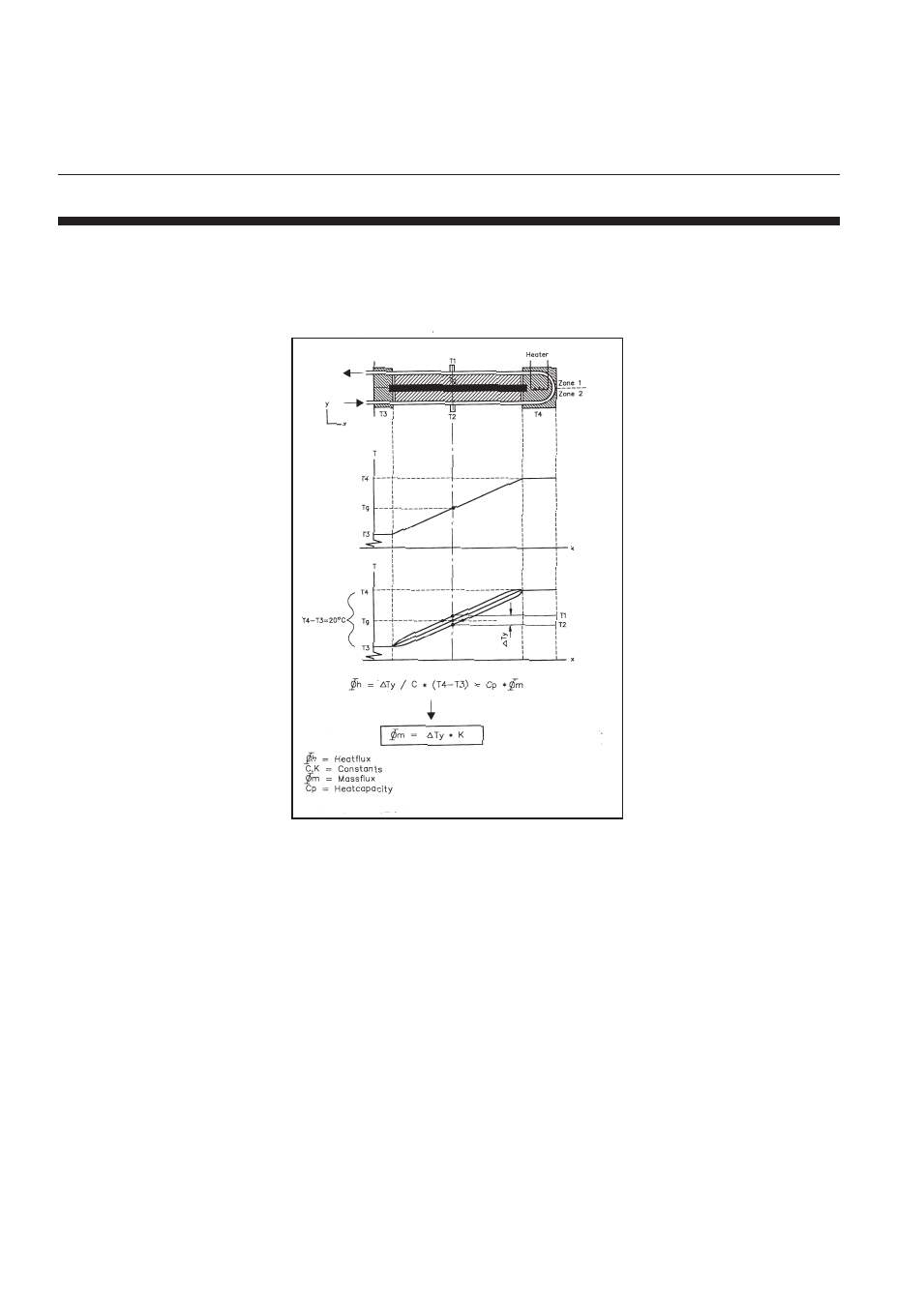
Figure 3-1 shows the lay-out of the sensor. The temperature difference between heater and bottom of the
sensor is regulated to a constant of 10 or 20 °C. To ensure a constant heat-gradient (linearity) along the
tube, a high conductive strip (guideline) is added. A fixed conductance from the pipes to the guideline is
realized with a so-called interface material. The temperature T1 - T2 reflects the heat current to and from
the liquid. As can be seen, T1 - T2 is proportional to the liquid flow thru the sensor and the heat-gradient
at T1, T2.
Figure 3-1 Measurement Principle 5891
3-1
Theory of Operation
(refer to figures 3-1 and 3-2)
Section 3 Theory of Operation