Brooks, Model 5861 i – Brooks Instrument 5861i User Manual
Page 35
4-11
Installation and Operation Manual
X-TMF-5861i-MFC-eng
Part Number: 541B111AAG
November, 2008
Brooks
®
Model 5861
i
Section 4 Maintenance
The Model 5861
i Mass Flowmeter utilizes porous metal restrictor
assemblies for all full scale flow rates. Restrictor elements with porosities
of 40 and 60 microns are used in different combinations. Up to three
restrictor elements can be placed in one assembly. These restrictors are
assembled by pressing the porous metal elements into the header plate.
When sizing a restrictor assembly for gases other than nitrogen, the
sensor conversion factor must be used to calculate a nitrogen equivalent
flow rate. Use the following equation to obtain the desired flow in nitrogen
equivalent units. Refer to Table 4-3 for the conversion factor list.
N
2
equivalent
=
desired gas flow
sensor conversion factor
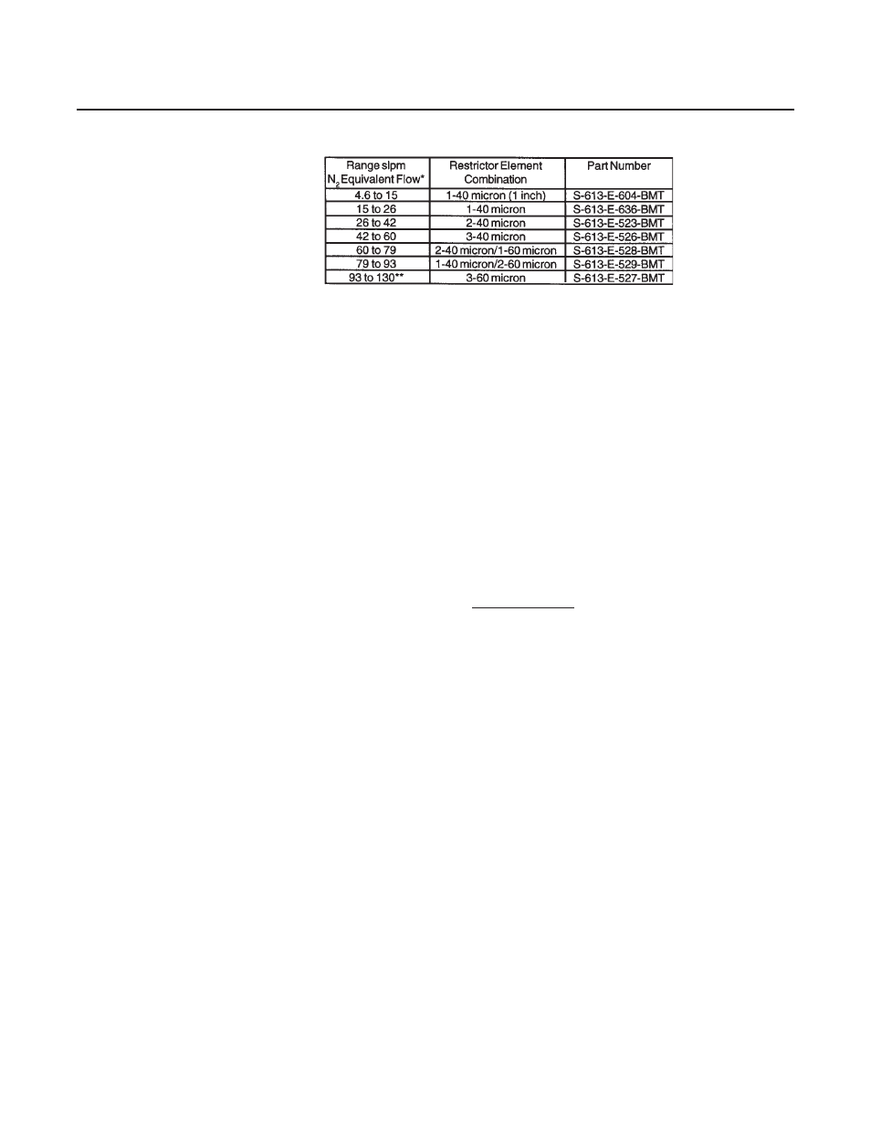
Using this Nitrogen equivalent flow, select a restrictor assembly from Table
4-4.
Example:
The desired gas is cyanogen
The desired full scale flow rate is 30 slpm.
Sensor conversion factor is 0.498 from Table 4-3.
Nitrogen equivalent flow = 30/0.498 = 60.24 slpm
In the previous example , the restrictor should be sized for a 60.24 slpm
flow rate (P/N S613E528BMT).
If a restrictor assembly is being replaced because the original has become
contaminated, the original may be used as a guide to select the
replacement assembly. The porosity of the original element or elements is
marked on the calibration sheet which was shipped with the flowmeter. The
replacement assembly should be replaced in the same orientation as the
original restrictor. (Refer to Section 4-4 for assembly procedure).
Table 4-4 Restrictor Selection Guide
Based on 0
0
C Standard Reference Temperature
**For Hydrogen from 130 slpm to 200 slpm use 3-60
micron restrictor elements.
Note: If the Nitrogen equivalent flow is between two
sizes, choose the larger size.