Draw-Tite 118413 T-ONE CONNECTOR User Manual
Draw-Tite For the car
4. Route the
T-Connector end with
green
wire to the passenger's side
. Repeat step
3 on the passenger's side with T-connector
end containing the
green wire
.
5. Locate the e
xisting ground stud. Loosen
bolt, place screw eyelet on stud and
re-tighten bolt
h
&
j
.
W
ARNING
All connections m
ust be complete for the
T-Connector to function properly. Test and
verify installation with a test light or trailer
once installed.
6. Mount the
T-connector
b
lack
bo
x using
double-sided tape provided
i
&
j
.
Secure the remainder of the T-connector
harness with the cable ties provided. To
prevent damage or rattling, be careful to
avoid any areas that would cut or pinch the
wire.
7. Reposition the access panels
, trays and
trunk floor panels and reattach the
threshold.
NO
TE
Store 4-Flat in tr
unk or rear cargo area
when not in use.
W
ARNING
Ov
erloading circuit can cause fires. DO
NOT exceed lower of towing manufacturer
rating or:
• Max. stop/turn light: 1 per side (2.1 amps)
• Max. tail lights: (4.2 amps)
Read vehicle's owners manual &
instruction sheet for additional information.
ENGLISH
TOOLS NEEDED
8mm, 10mm and 13mm Soc
ket &
Ratchet or 8mm, 10mm and 13mm
Wrench,Test Probe, Trim Panel Remover
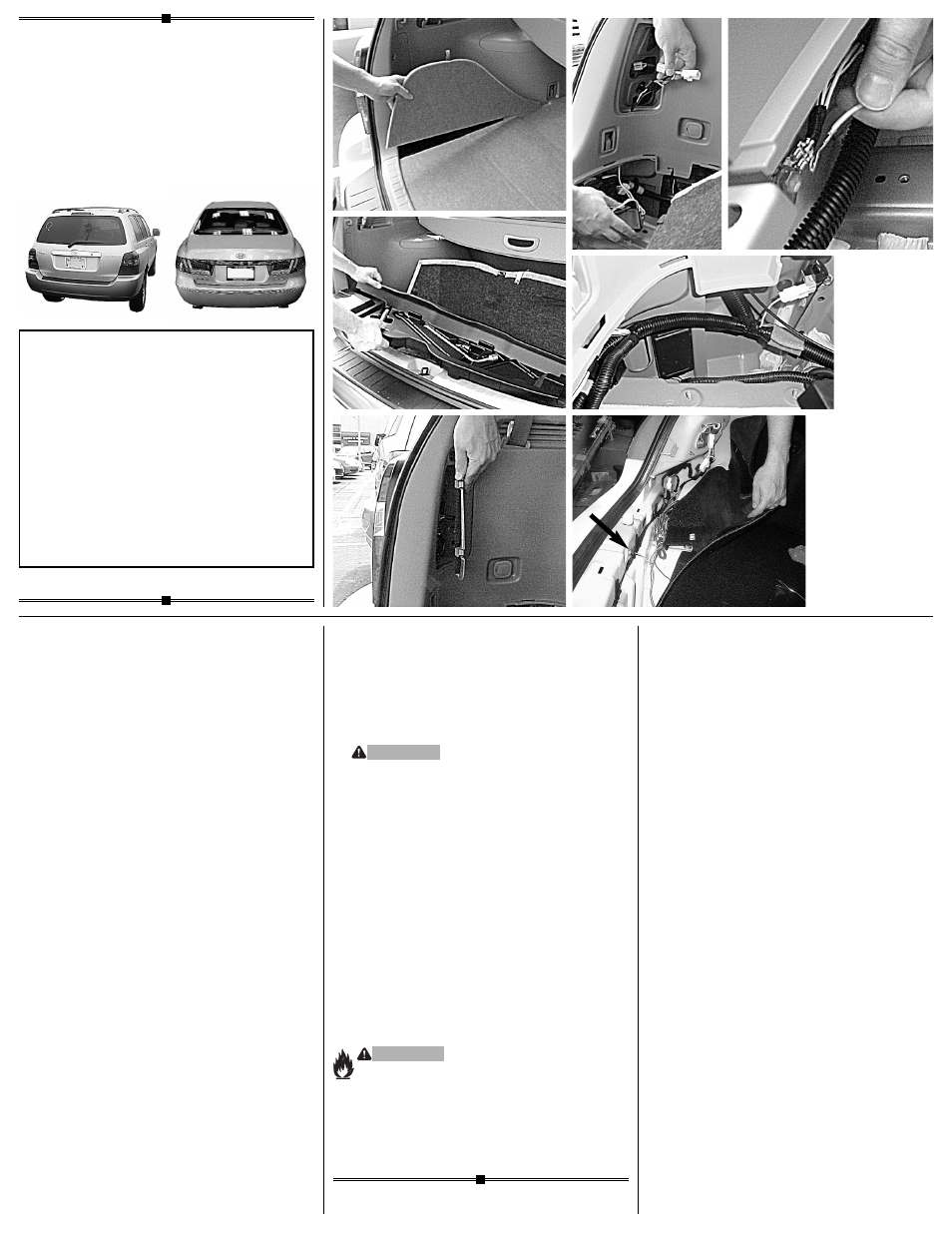
1.
Highlander
Open the v
ehicle’s rear tailgate. On the
driver’s side remove access panel to
locate rear of taillight
d
.
Repeat on the
passenger side. Remove threshold, trunk
floor panels and trays
e
.
Set aside all
items removed being careful not to
damage parts.
Az
era
Open tr
unk and remove threshold
panel. Partially remove the felt trunk
liner on driver’s side, exposing the
taillight wiring
j
.
2. On the dr
iver and passenger sides of the
vehicle, locate the vehicle's taillight wiring
harness
f
&
j
.
The taillight wiring har-
ness will have a connection point, on both
sides, matching the ends of the T-
Connector. Separate these connectors,
being careful not to break the locking tabs.
All connector surfaces should be clean and
free of dirt.
3. On the dr
iver’s side insert the T-Connector
end, with the
y
ellow
wire
, between the
vehicle wiring connectors and lock into
place
g
&
j
.
Be sure that connectors
are fully inserted with locking tabs in place.
118413-037
Rev. A
06/01/06
•
d
•
e
•
g
•
j
•
f
•
i
•
h
READ
THIS FIRST:
Read and f
ollow all vehicle warnings and
installation instructions before beginning
installation. Wear safety glasses and use
all safety precautions during installation.
LISEZ CECI EN PREMIER:
Lire et obser
ver toutes les consignes de sécurité
et les instructions avant de commencer l’installa-
tion. Durant l’installation, veiller à toujours porter
des lunettes de protection et respecter les
mesures de sécurité.
LEA
ESTO PRIMERO:
Lea y siga todas las adv
ertencias e instrucciones
de instalación del vehículo antes de empezar la
instalación. Use gafas de seguridad y todas las
precauciones de seguridad durante la instalación.
Installation Instr
uctions
Directives de Montage
Instrucciones de Instalación
T-Connector
Connecteur en T
Conector en T