Draw-Tite 118507 T-ONE CONNECTOR User Manual
Di h g
READ THIS FIRST:
Read and follow all vehicle warnings and
installation instructions before beginning installation.
Wear safety glasses and use all safety precautions
during installation.
LISEz CECI En PREmIER:
Lire et observer toutes les consignes de sécurité et les
instructions avant de commencer l’installation. Durant
l’installation, veiller à toujours porter des lunettes
de protection et respecter les mesures de sécurité.
LEA ESTO PRImERO:
Lea y siga todas las advertencias e instrucciones
de instalación del vehículo antes de empezar la
instalación. Use gafas de seguridad y todas las
precauciones de seguridad durante la instalación.
118507-037
Rev. A
7/29/2010
Installation Instructions
Directives de montage
Instrucciones de Instalación
T-Connector
Connecteur en T
Conector en T
Lincoln mKT
e
f
ENGLISH
TOOLS REQUIRED:
Drill (3/32” Drill Bit), Philips Head Screwdriver,
Wire Cutters, 10mm Socket & Ratchet
or 10mm Wrench
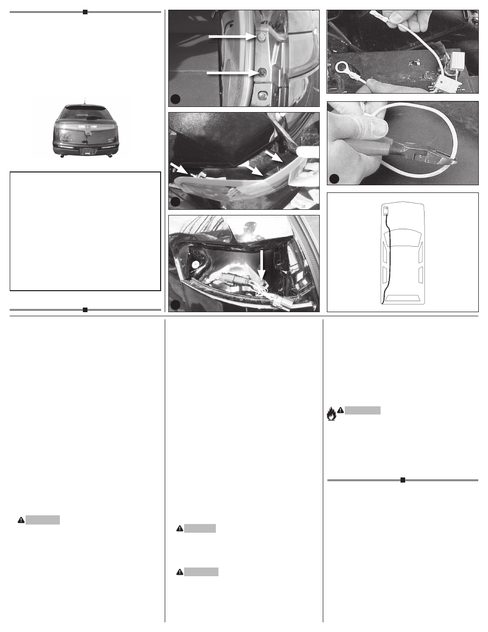
1. Open rear door. Remove both taillight housing
assemblies by removing the two bolts for each
light and carefully prying the vehicle taillight
housing assembly away from the vehicle, being
careful not to break the alignment tabs de.
2. On the driver’s side, disconnect the vehicle
wiring harness from the taillight socket. Plug
the T-Connector end with the yellow wire in-
between the mating plugs on the driver’s side
taillight socket and vehicle wiring harness.
3. On the driver’s side, route the T-Connector end
with the green wire and the wire with the 4-Flat
connector down through the opening between
the vehicle bumper and body f.
4. Route the T-Connector end with green wire to
the passenger’s side and route the 4-Flat under-
neath the bumper.
WARnInG
Route the wire being careful to avoid any hot
pipes, heat shields, the fuel tank or any other
points that may pinch or break the wire.
Route T-Connector end with green wire up
through the opening on the passenger side,
being careful to avoid areas that could damage
wiring. Repeat step 2 for T-Connector end with
the green wire.
5. Disconnect and isolate the vehicle’s negative
battery terminal g. If not removed, remove the
fuse from the supplied fuse holder. After cutting
the fuse holder wire, attach the ring terminal
and secure to the vehicle’s Positive (+) battery
cable gh. Connect the other end of the fuse
holder to the black 12 ga. wire included, using
the supplied Yellow butt connector.
6. Beginning from the front of the vehicle, route
the black 12 ga. wire rearward along the frame
rail avoiding any hot pipes, heat shields, the fuel
tank or any other points that may pinch or break
the wire i. On the driver’s side, locate the Red
12 ga. Power wire from the T-Connector box.
Connect to Black wire using the supplied Yellow
butt connector.
7. Locate a suitable grounding point near the
connector such as the vehicle’s frame or cross
member. (Do not drill into vehicle floor or bed.)
Clean dirt and rustproofing from area. Drill a
3/32” hole and secure white wire using eyelet
and screw provided. Reconnect the vehicle’s
Negative (-) battery cable and install the 10 amp
fuse into the fuse holder from step 5.
CAUTIOn
Verify what is behind any surface prior to
drilling to avoid damage to the vehicle and/or
personal injury. Do not drill into any exposed
surfaces.
WARnInG
All connections must be complete for the
T-Connector to function properly. Test and
verify installation with a test light or trailer once
installed.
8. Reinstall the taillight housing assemblies,
positioning the vehicle wiring harness between
the housing and the vehicle body. Secure the
remainder of the T-connector harness with the
cable ties provided, to prevent damage or
rattling and being careful to avoid any areas that
would cut or pinch the wire.
nOTE
Mount 4-Flat in a suitable location
under the vehicle. Bracket not included.
WARnInG
Overloading circuit can cause fires.
DO NOT exceed lower of towing
manufacturer rating or:
• Max. stop/turn light: (2.1 amps)
• Max. tail lights: (5.6 amps)
Read vehicle’s owners manual &
instruction sheet for additional information.
d
i
h
g