Draw-Tite 118397 T-ONE CONNECTOR User Manual
Draw-Tite For the car
11. Reinstall the plastic tr
im panels, threshold,
storage covers, floor covering and other
items that may have been removed during
installation, being careful not to pinch or
cut the wires.
NO
TE:
Store 4-Flat connector in spare tire
compartment when not in use.
W
ARNING
All connections m
ust be complete for the
T-Connector to function properly. Test and
verify installation with a test light or trailer
once installed.
W
ARNING
Ov
erloading circuit can cause fires. DO NOT
exceed lower of towing manufacturer rating or:
• Max. stop/turn light: 1 per side (2.1 amps)
• Max. tail lights: (5 amps)
Read vehicle's owners manual & instruction
sheet for additional information.
ENGLISH
Tools Required:
T
rim Panel Remover, Philips Head Screwdriver,
Drill (3/32" Drill Bit), 10mm Socket & Ratchet or
10mm Wrench
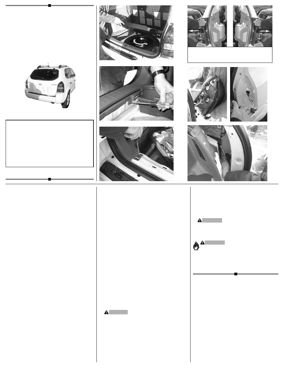
1.
Open rear hatch.
Temporarily remove all floor
coverings, 10 mm storage tray bolts and storage
trays, exposing the spare tire compartment
d
.
After removing two screws
e
, carefully use a
trim panel tool to pry the threshold plate away
from the vehicle, being careful not to damage any
clips. Remove two screws in the threshold plate
area
f
, to gain access behind tr
im panels.
Being careful not to damage clips, partially
remove the lower interior trim panels on each
side of the vehicle. Set aside all items removed
being careful not to damage parts.
NO
TE:
It is not necessar
y to remove any of the
cargo net holders.
2.
Remo
ve the taillights on both the driver and
passenger side of the vehicle. After removing
the three screws, carefully pull the tailight away
from the vehicle being careful not to damage
the alignment pins
g
.
3.
On the dr
iver and passenger taillights, locate the
vehicle's taillight wiring harness
h
.
The taillight
wiring harness will have a connection point, on
both sides, matching the ends of the T-Connector.
Separate this connector, being careful not to
break the locking tabs. All connector surfaces
should be clean and free of dirt.
4.
On the dr
iver and passenger sides
i
, star
ting
with the grommet, push the vehicle's taillight
wiring harness into rear cargo compartment,
behind the partially removed trim panels
j
.
18397-037
Rev. A
02/02/05
Installation Instr
uctions
Directives de Montage
Instrucciones de Instalación
T-Connector
Connecteur en T
Conector en T
READ
THIS FIRST:
Read and f
ollow all instructions carefully before
beginning installation.
LISEZ CECI EN PREMIER:
Lire et suivre toutes les instr
uctions
attenrivement avant le montage.
LEA
ESTO PRIMERO:
Lea y siga todas las instr
ucciones cuidadosamente
antes de iniciar la instalación.
5.
F
rom inside the rear cargo compartment on
the passenger side, locate the vehicle's taillight
wiring harness behind the partially removed
trim panels
j
.
Insert the T-Connector end with
the
green wire into the v
ehicle’s taillight wiring
connector and lock into place. Be careful not
to damage the locking tabs and be sure that
connectors are fully inserted with locking
tabs in place.
6.
Route the
T-Connector end with the
green
wire and g
rommet out of the opening exposed
in step 4. From outside of the vehicle, pull
T-Connector end until the grommet on the
harness reaches the opening. Seat the
grommet in opening.
7.
Inser
t the T-Connector end with the
green wire
into the vehicle’s taillight connector and lock into
place. Be careful not to damage the locking tabs
and be sure that connectors are fully inserted
with locking tabs in place.
8.
Route the
T-Connector end with the
y
ellow
wire
to the driver’s side behind the panels and along
the threshold. Repeat Steps 5 thru 7 using
T-Connector containing the
y
ellow
wire
.
9.
Locate a suitab
le grounding point near the
connector. Drill a 3/32" hole and secure the
white wire using the e
yelet and screw
provided
j
.
CA
UTION
V
erify what is behind any surface prior to drilling
to avoid damage to the vehicle and/or personal
injury. Do not drill into any exposed surfaces.
10. Mount the
T-Connector Black Box using the
double-sided tape provided. Secure the
remainder of the T-Connector harness with
the cable ties provided, to prevent damage
or rattling and being careful to avoid any
areas that would cut or pinch the wire.
•
d
•
e
•
i
•
j
•
g
•
g
•
f
•
h
CA
UTION
Carefully remo
ve in this direction.
A
TTENTION
Retirer délicatement dans ette direction.
A
TENCIÓN
Retire cuidadosamente en esta dirección.