Draw-Tite 118551 T-ONE CONNECTOR User Manual
Kh j, Id e g f, English
Installation Instructions
Directives de Montage
Instrucciones de Instalación
T-Connector
Connecteur en T
Conector en T
Page 1
Ford Edge
Instructions begin on Page 1
Les instructions commencent à la Page 2
Las instruciones empiezan en la Página 2
Mercury Mariner
Instructions begin on Page 1
Les instructions commencent à la Page 2
Las instruciones empiezan en la Página 2
Ford Escape
Instructions begin on Page 1
Les instructions commencent à la Page 2
Las instruciones empiezan en la Página 2
Ford Econoline
Instructions begin on Page 1
Les instructions commencent à la Page 2
Las instruciones empiezan en la Página 2
Lincoln MKX
Instructions begin on Page 1
Les instructions commencent à la Page 2
Las instruciones empiezan en la Página 2
Mazda Tribute
Instructions begin on Page 1
Les instructions commencent à la Page 2
Las instruciones empiezan en la Página 2
ENGLISH
FORD EDGE / LINCOLN MKX ONLY
TOOLS REQUIRED:
Trim Panel Remover, 10mm Socket & Ratchet
or 10mm Wrench, 20mm Socket & Ratchet
or 20mm Wrench, Drill (3/32” Drill Bit),
1/4” socket, Wire Crimpers, Wire Cutters,
Philips Head Screwdriver, Test-probe
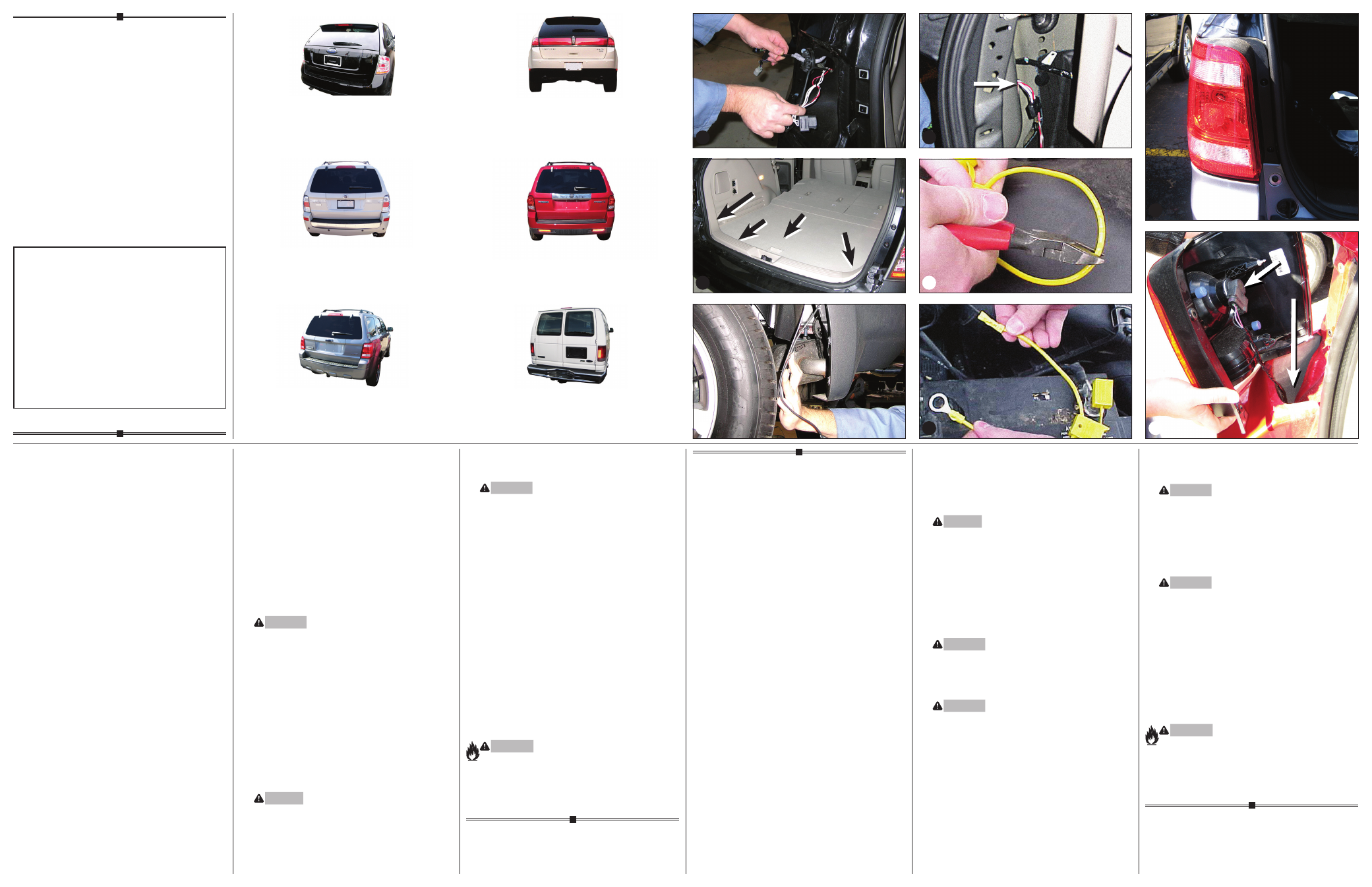
1. Open the rear tailgate to access the bolts that
hold the taillights in place. Remove two bolts and
carefully pry the taillight housings rearward away
from the vehicle, being careful not to break the
alignment tabs.
2. On both the driver’s and passenger’s side,
pull the vehicle taillight wire harness and unseat
the grommet d.
3. Inside the vehicle’s rear cargo area, temporarily remove
all floor coverings, cargo trays and plastic threshold
cover. Partially remove side trim panels, being careful
not to damage clips or screws e.
4. Behind the side trim panel on the Driver’s side, route
the T-Connector end with the yellow/brown wires out
of the opening exposed in step 2 dg.
5. Beginning on the driver’s side, separate the vehicle’s
wiring connectors, being careful not to break the
locking tabs. Check to see that the mating surfaces of
the vehicle wiring connectors match the T-Connector
ends. Ensure that the mating surfaces are free of dirt.
Plug the T-Connector harness ontaining the yellow/
brown wires in between the vehicle’s mating
connectors. Ensure that the connectors are fully
inserted with locking tabs in place.
6. Route the T-Connector containing the green wire
below the threshold cover to the passenger’s side
taillight housing.
7. Repeat step 5 for the passenger’s side using the
T-Connector containing the green wire.
8. On the driver’s side, in rear wheel well, partially remove
wheel well and mud guard f.
9. From the driver’s side taillight pocket, route one end of
the black wire thru the opening exposed in step 2 to
the T-Connector’s black box. Connect to red wire on
T-Connector’s black box with the supplied yellow butt
connector. Route the other end down thru the opening
in the taillight pocket, behind the bumper d.
10. From behind wheel well exposed in step 8, locate the
black wire. Route the black wire along the exterior
frame or follow the existing wiring along the thresholds
into the engine compartment up to the battery avoiding
areas that may pinch or break the wire f.
WARNING
Route the wire being careful to avoid any hot pipes,
heat shields, the fuel tank or any other points that
may pinch or break the wire.
11. Disconnect the vehicle’s Negative (-) battery cable.
If not removed, remove the fuse from the yellow fuse
holder (provided). After cutting the fuse holder wire,
attach the ring terminal and secure to the vehicle’s
Positive (+) battery cable hi. Connect the other end
of the fuse holder to the black 12 ga. wire, using the
yellow butt connector (provided).
12. Locate a suitable grounding point near the connector
such as an existing ground stud or drill a 3/32” hole
and secure the white wire using the eyelet and screw
provided. (Do not drill into vehicle floor or bed.) Clean
dirt and rustproofing from area g.
CAUTION
Verify what is behind any surface prior to drilling to
avoid damage to the vehicle and/or personal injury.
Do not drill into any exposed surfaces.
13. Reconnect the vehicle’s Negative (-) battery cable
and install the 15 amp fuse into the fuse holder
from step 11.
WARNING
All connections must be complete for the T-Connector
to function properly. For initial test, reset vehicle
electrical system by temporarily removing the key from
the ignition. Test and verify installation with a test light
or trailer once installed.
14. On both the driver’s and passenger’s side,
slit the grommet to allow for T-Connector’s wiring.
Reseat grommet.
15. Secure the remainder of the T-connector harness
with the cable ties provided, to prevent damage or
rattling and being careful to avoid any areas that would
cut or pinch the wire. In the driver’s side storage area,
clean a flat area using a mixture of rubbing alcohol
and water g.
16. Mount the T-Connector black box using double-sided
tape provided.
17. Reinstall wheel wells, mud guards, taillights and other
items removed during installation, being careful not to
pinch or cut the wires.
NOTE
Store 4-Flat connector in rear cargo area when not
in use.
WARNING
Overloading circuit can cause fires. DO NOT exceed
lower of towing manufacturer rating or:
• Max. stop/turn light: 2 per side (4.2 amps)
• Max. tail lights: (7.5 amps)
Read vehicle’s owners manual & instruction sheet for
additional information.
Installation Continued: Page 2
Installation (suite): Page 2
Instalación continuación: Página 2
ENGLISH
MERCURY MARINER, FORD ESCAPE,
MAZDA TRIBUTE, FORD ECONOLINE
VAN ONLY
TOOLS REQUIRED:
Drill (3/32” Drill Bit), 1/4” socket, Wire Crimpers,
Wire Cutters, Philips Head Screwdriver, Test-probe
1. Open the rear tailgate to access the screws that
hold the taillights in place. Remove the screws and
carefully pry the taillight housings rearward away
from the vehicle, being careful not to break the
alignment tabs. j
2. Disconnect the vehicle wiring harness from both
taillight sockets k. Plug the T-Connector end with
the yellow/brown wires in-between the mating plugs
on the driver’s side taillight socket and vehicle
wiring harness. All connector surfaces should be
clean and free of dirt. Ensure that the connectors
are fully inserted with locking tabs in place.
3. On the driver’s side, route the T-Connector end with
the green wire and the wire with the 4-Flat connector
down through the opening between the vehicle bumper
and body k. Route the T-Connector end with green
wire to the passenger’s side and route the 4-Flat
underneath the bumper. Route T-Connector end with
green wire up through the opening on the passenger
side, being careful to avoid any hot pipes, heat shields,
the fuel tank or any other points that may pinch or
brake the wire. Repeat step 2 for the passenger’s side
using the T-Connector containing the green wire.
4. Locate a suitable grounding point near the connector
such as the vehicle’s frame or cross member.
(Do not drill into vehicle floor or bed. Do not drill into
any exposed surfaces.) Clean dirt and rustproofing
from area. Drill a 3/32” hole and secure white wire
using eyelet and screw provided.
CAUTION
Verify what is behind any surface prior to drilling to
avoid damage to the vehicle and/or personal injury.
Do not drill into any exposed surfaces.
5. Disconnect the vehicle’s Negative (-) battery cable.
If not removed, remove the fuse from the yellow fuse
holder (provided). After cutting the fuse holder wire,
attach the ring terminal and secure to the vehicle’s
Positive (+) battery cable hi. Connect the other end
of the fuse holder to the black 12 ga. wire, using the
yellow butt connector (provided).
WARNING
Read and follow all warnings and cautions printed on
the tow vehicle’s battery.
6. Beginning from the front of the vehicle, route the black
12 ga. wire rearward along the frame rail.
WARNING
Route the wire being careful to avoid any hot pipes,
heat shields, the fuel tank or any other points that may
pinch or break the wire.
7. Route the black 12 ga. wire to the rear driver’s side.
Locate the opening between the vehicle rear bumper
and body allowing entry to the rear driver’s side
taillight area. Route the wire up through this hole
and attach the black 12 ga. wire to the red wire from
the T-Connector black box with the supplied yellow
butt connector.
8. Reconnect the vehicle’s Negative (-) battery cable
and install the 15 amp fuse into the fuse holder
from step 5.
WARNING
All connections must be complete for the T-Connector
to function properly. For initial test, reset vehicle
electrical system by temporarily removing the key from
the ignition. Test and verify installation with a test light
or trailer once installed.
9. Mount the T-Connector black box using
double-sided tape provided.
WARNING
Make sure module is mounted so that the epoxy side
of the module is pointed towards the ground to prevent
any water buildup.
10. Reinstall the taillight housing assemblies, positioning
the vehicle wiring harness between the housing and the
vehicle body. Secure the remainder of the T-Connector
harness under the bumper with cable ties provided,
being careful to avoid any areas that would cut or
pinch the wire.
NOTE
Mount 4-Flat in a suitable location under the vehicle.
Bracket not included.
WARNING
Overloading circuit can cause fires. DO NOT exceed
lower of towing manufacturer rating or:
• Max. stop/turn light: 2 per side (4.2 amps)
• Max. tail lights: (7.5 amps)
Read vehicle’s owners manual & instruction sheet for
additional information.
k
h
j
118551-037
Rev. A
07/06/11
READ THIS FIRST:
Read and follow all vehicle warnings and installation
instructions before beginning installation. Wear safety
glasses and use all safety precautions during installation.
LISEZ CECI EN PREMIER:
Lire et observer toutes les consignes de sécurité et les
instructions avant de commencer l’installation. Durant
l’installation, veiller à toujours porter des lunettes de
protection et respecter les mesures de sécurité.
LEA ESTO PRIMERO:
Lea y siga todas las advertencias e instrucciones de
instalación del vehículo antes de empezar la instalación.
Use gafas de seguridad y todas las precauciones de
seguridad durante la instalación.
i
d
e
g
f