Draw-Tite 118585 T-ONE CONNECTOR User Manual
Draw-Tite For the car
ENGLISH
TOOLS REQUIRED:
6mm hex wrench, Philips Head Screwdriver,
Test-probe, Wire Cutters
NOTE
Due to the variance in vehicle options, there
could be alternate installation methods required.
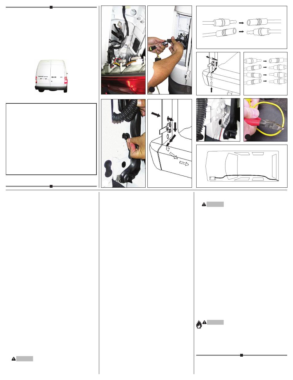
1. Open rear door. Beginning on the driver’s side, using a
6mm hex wrench. Remove two bolts and carefully pry
the taillight housings rearward away from the vehicle,
being careful not to break the alignment tabs. Repeat
on the passenger side.
2. On the driver and passenger sides of the vehicle,
locate the vehicle’s taillight wiring harness d. The
taillight wiring harness will have a connection point,
on both sides, matching the ends of the T-Connector.
Separate this connector, being careful not to break the
locking tabs. All connector surfaces should be clean
and free of dirt.
3. Beginning on the driver’s side, plug the T-Connector
harness containing the
yellow wire in between the
vehicle’s mating connectors e.
4. Repeat step 3 for the passenger’s side using the
T-Connector containing the
green wire.
5. Beginning on the driver’s side. Locate black plug above
door hinge and temporarily remove to expose hole f.
Remove the same plug on the passenger side.
Beginning on the driver’s side. Route the wires
containing the
green and red wire out the hole and
route down through the opening behind the bumper
and across to the passenger side g. Route back
up through the opening behind the bumper and in
through the hole into the passenger side pocket.
WARNING
Route the wire being careful to avoid any hot pipes,
heat shields, the fuel tank or any other points that may
pinch or break the wire.
6. Plug the green wire and red wire to the corresponding
wire on the harness from step 4 h.
7. Route the 4-Flat through the driver’s side trim panel
into side storage compartment and store there when
not in use.
NOTE
If jack storage is not accessible, then from underneath
the vehicle, route the harness with the 4-plugs up
through the opening behind the driver’s side bumper
into the hole and into the driver’s side pocket i.
Plug the 4 wires to the corresponding wire on the
harness from step 7 j.
NOTE
Mount the 4-Flat end in an accessible location with
a bracket or electrical box (not included).
8. Locate existing ground stud. Loosen bolt, place screw
eyelet on stud and re-tighten bolt. Make sure all other
ground connections are secure when removing and
reattaching the ground stud.
9. Disconnect the vehicle’s Negative (-) battery cable.
If not removed, remove the fuse from the yellow fuse
holder (provided). After cutting the fuse holder wire,
attach the ring terminal and secure to the vehicle’s
Positive (+) battery cable. Connect the other end of
the fuse holder to the
black 12 ga. wire, using the
yellow butt connector (provided). l
10. Either route the black wire thru a grommet and along
the exterior frame or follow the existing wiring along
the thresholds into the engine compartment up to the
battery avoiding areas that may pinch or break the
wire. m
11. Connect the other end of the black 12 ga. wire to the
black power wire located on the T-Connector’s black
box, using the yellow butt connector (provided).
12. Reconnect the vehicle’s Negative (-) battery cable and
install the 15 amp fuse into the fuse holder from step 9.
WARNING
All connections must be complete for the T-Connector
to function properly. Test and verify installation with a
test light or trailer once installed. For initial test, reset
vehicle electrical system by temporarily removing the
key from the ignition.
13. Behind the taillight assembly on the Driver’s side,
clean a flat area using a mixture of rubbing alcohol
and water.
NOTE
Make sure that the tail light assembly can be
reinstalled before mounting black box. Mount
the black box in this area using the double-sided
tape provided.
14. In the area shown on both sides of the vehicle,
clean the area using the mixture of rubbing alcohol
and water. Using the silver tape provided, attach
the the
green and red wire to the area cleaned
and secure it so that it won’t get damaged. k
15. Take the black plugs removed in step 5, notch
each of them to allow the wires to pass through,
then reinstall the plug and seal plug accordingly.
16. Secure all loose wires with cable tie provided.
Reinstall the taillight removed in step 1.
WARNING
Overloading circuit can cause fires. DO NOT exceed
lower of towing manufacturer rating or:
• Max. stop/turn light: 2 per side (4.2 amps)
• Max. tail lights: (7.5 amps)
Read vehicle’s owners manual & instruction sheet for
additional information.
READ THIS FIRST:
Read and follow all vehicle warnings and
installation instructions before beginning installation.
Wear safety glasses and use all safety precautions
during installation.
LISEZ CECI EN PREMIER:
Lire et observer toutes les consignes de sécurité et les
instructions avant de commencer l’installation. Durant
l’installation, veiller à toujours porter des lunettes
de protection et respecter les mesures de sécurité.
LEA ESTO PRIMERO:
Lea y siga todas las advertencias e instrucciones
de instalación del vehículo antes de empezar la
instalación. Use gafas de seguridad y todas las
precauciones de seguridad durante la instalación.
118585-037
Rev. A
3/12/2013
Installation Instructions
Directives de Montage
Instrucciones de Instalación
T-Connector
Connecteur en T
Conector en T
Ford Transit Connect
e
g
i
j
k
l
m
f
d
h