Draw-Tite 118417 T-ONE CONNECTOR User Manual
Draw-Tite For the car
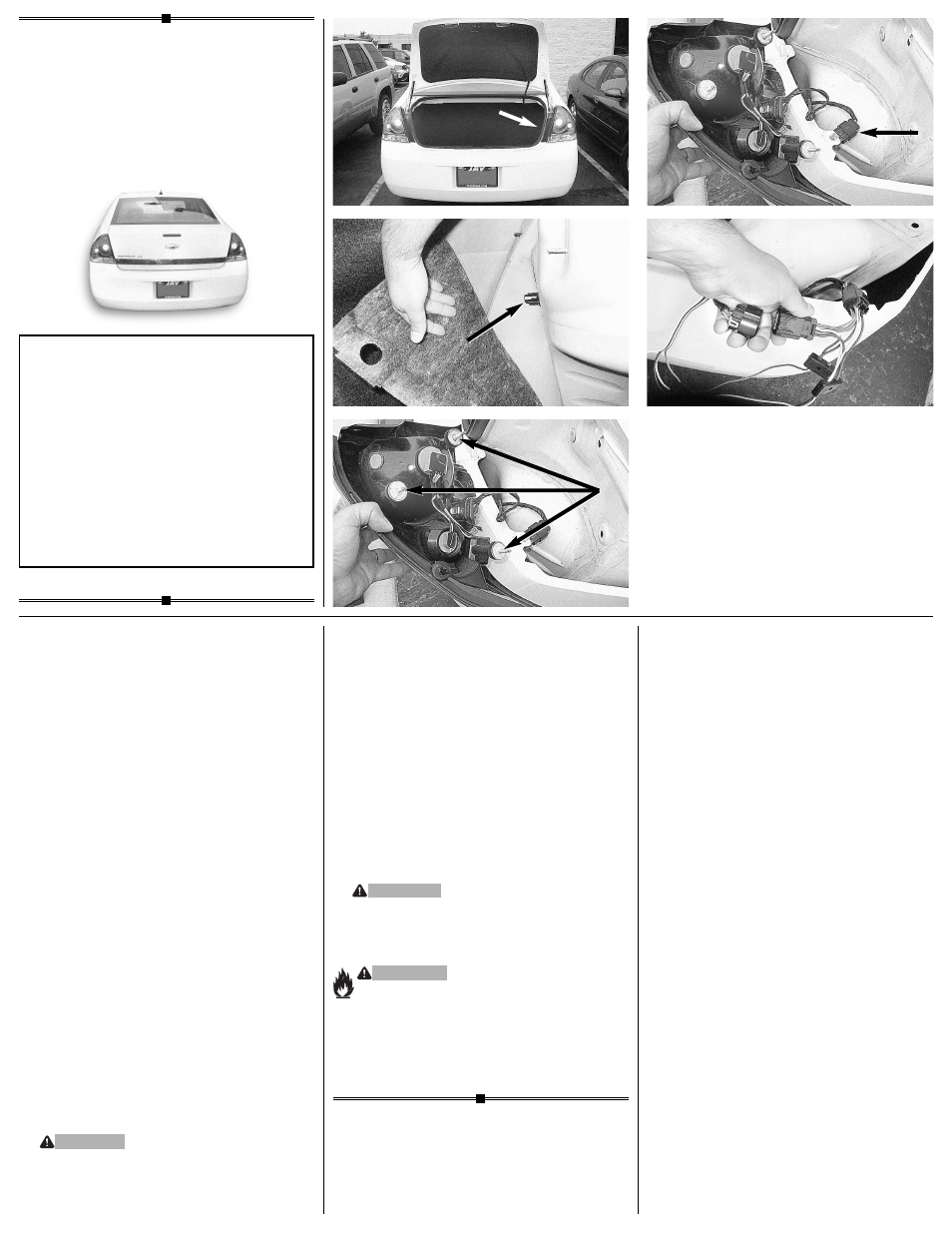
4. Route the
T-Connector end with the 4-Flat
down through the taillight pocket between
the bumper and body and towards the
center of the bumper. Secure wires with
cable ties provided.
5. Reinstall the taillight housing assemb
lies,
positioning the vehicle wiring harness
between the housing and the vehicle body.
Reinstall the plastic wing nuts, carpet and
threshold and any other items that were
removed during installation, being careful
not to pinch or cut the wires. Secure the
remainder of the T-Connector harness with
the cable ties provided, to prevent damage
or rattling and being careful to avoid any
areas that would pinch, cut or melt the wire.
W
ARNING
All connections m
ust be complete for the
T-Connector to function properly. Test and
verify installation with a test light or trailer
once installed.
W
ARNING
Ov
erloading circuit can cause fires.
DO NOT exceed lower of towing
manufacturer rating or:
• Max. stop/turn light: 1 per side (7.5 amps)
• Max. tail lights: (7.5 amps)
Read vehicle's owners manual &
instruction sheet for additional information.
ENGLISH
TOOLS NEEDED
T
rim Panel Remover, Drill (3/32” Drill Bit),
1/4" socket
1. Open the tr
unk to remove the passenger's
side vehicle taillight assembly
d.
Using a
trim panel tool, carefully pry the threshold
plate away from the vehicle, being careful not
to damage any clips. Carefully pull the carpet
back on the passenger side to expose the
plastic wing nuts for passenger's side taillight
e.
Remove the wing nuts on passenger
side, then carefully pull the taillight away
from the vehicle being careful not to damage
the alignment pins
f.
2. Disconnect the wir
ing harness at the plugs
located in the taillight pocket
g.
Check to
see that the mating surfaces of the vehicle
wiring connectors match the T-Connector
ends. All connector surfaces should be
clean and free of dirt. Plug the T-Connector
in-between the mating plugs
h.
Be careful
not to damage the locking tabs and be sure
that connectors are fully inserted with locking
tabs in place.
3. Locate a suitab
le grounding point near the
connector such as an existing ground stud
or drill a 3/32” hole and secure the
white
wire using the e
yelet and screw provided.
(Do not drill into vehicle floor or bed.) Clean
dirt and rustproofing from area.
CA
UTION
V
erify what is behind any surface prior to
drilling to avoid damage to the vehicle and/
or personal injury. Do not drill into any
exposed surfaces.
118417-037
Rev. A
08/24/06
•
d
•
e
•
f
•
g
•
h
READ
THIS FIRST:
Read and f
ollow all vehicle warnings and
installation instructions before beginning
installation. Wear safety glasses and use
all safety precautions during installation.
LISEZ CECI EN PREMIER:
Lire et obser
ver toutes les consignes de sécurité
et les instructions avant de commencer l’installa-
tion. Durant l’installation, veiller à toujours porter
des lunettes de protection et respecter les
mesures de sécurité.
LEA
ESTO PRIMERO:
Lea y siga todas las adv
ertencias e instrucciones
de instalación del vehículo antes de empezar la
instalación. Use gafas de seguridad y todas las
precauciones de seguridad durante la instalación.
Installation Instr
uctions
Directives de Montage
Instrucciones de Instalación
T-Connector
Connecteur en T
Conector en T