Installation instructions, Gooseneck mounting kit ford f-450, Part numbers – Draw-Tite 4449 GOOSENECK RAIL KIT User Manual
Page 3
Installation Instructions
Part Numbers:
4449
6.
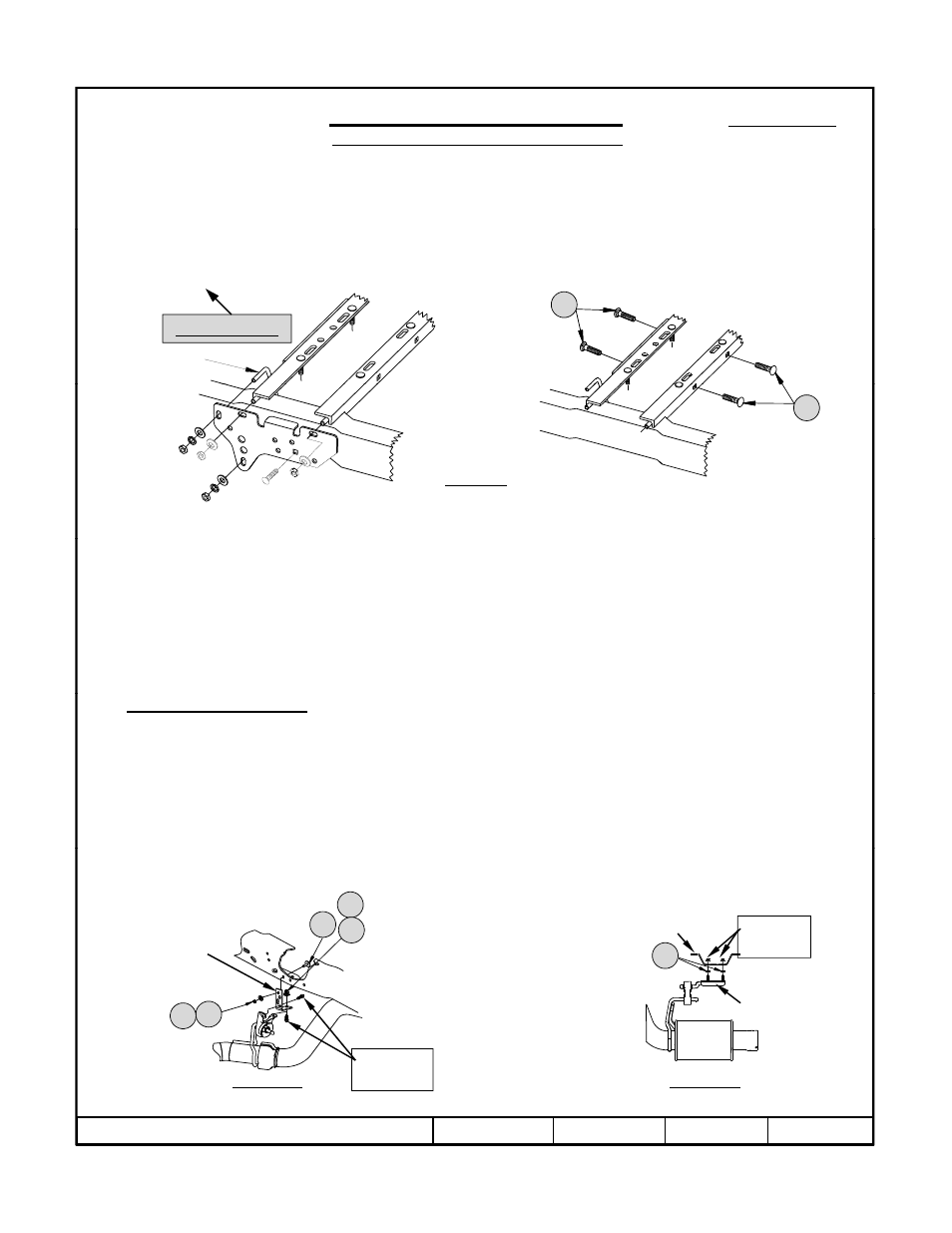
Loosely, hang the driver’s side and passenger’s side, hitch side brackets by attaching the 5/8” hardware to the threaded studs.
Install the 5/8 X 3.00 carriage bolts through the hitch side brackets, 5/8” blocks and large slots in the vehicle frame rails.
L
l i
ll h 5/8”
i l
h d
h
d 5/8 h
h
i
b l (
Fi
1)
GOOSENECK MOUNTING KIT
Ford F-450
Will not fit Cab-on-Chassis vehicles
Loosely, install the 5/8” conical toothed washers and 5/8 hex nuts onto the carriage bolts (see Figure 1).
7.
Use the supplied U-Bolt for the forward attachment of the bracket to the frame (see Figure 4). Position the U-Bolt from the
inside of the vehicle frame pointing towards the hitch side bracket. On the passenger’s side of the vehicle, the U-Bolt must be
positioned to the vehicle forward side of the shock mount and installed on an angle through the mounting slots on the hitch side
bracket.
Vehicle Forward
U-Bolt
20
8.
When installing the 9460/9470 Hide-A-Goose hitch, a hole must be drilled in the bed of the truck. Mark and drill a 1/4 inch
hole 46-3/16 inches from the rear of the bed and centered between the wheel wells. Using a hole saw, enlarge the pilot hole to
Figure 4
Additional
fasteners must
be used to
attach the hitch
see Figure 1.
20
hole 46 3/16 inches from the rear of the bed and centered between the wheel wells. Using a hole saw, enlarge the pilot hole to
the final diameter hole size. Refer to the 9460/9470 Hide-A-Goose hitch instruction sheet for hole size.
9.
Loosely install the 9460/9470 Hide-A-Goose hitch. Refer to the 9460/9470 instruction sheet and Figure 4 for mounting
locations.
10.
Align the sleeve of the Hide-A-Goose hitch with the hole drilled in the vehicle bed and torque the hitch fasteners to the cross
members to 212 ft.-lb. (287 N-m).
11.
Tighten the frame bracket and cross member fasteners to the required specification below.
Torque all 5/8-11 GR5 fasteners on the brackets and cross members to 150 ft.-lb. (203 N-m)
Torque all 1/2-13 fasteners on the brackets and cross member to 75 ft.-lb. (102 N-m)
12. On Gas Engine Vehicles Only Use the factory flange nut that was removed in Step 2 to tighten the tube holder onto the L-
bracket as shown in Figure 2d.
13. Install the safety chain kit as described in the 9460/9470 head instruction sheet.
14.
On some vehicles, the Hide-A-Goose handle may contact the emergency brake cable. The brake cable bracket should be
adjusted to provide clearance.
15.
Reinstall exhaust as shown below.
Exhaust installation:
16.
If there is less than ½” clearance between the exhaust pipe and the Hide-A-Goose cross members, the exhaust bracket
supplied with the 4449 mounting kit must be used. See figure 5a and 5b for 2008 models and up. For the rear attachment
(Figure 5a), fasten the supplied bracket extension to the factory bracket with the factory M8 bolts, then fasten the extension
Factory
nuts
Mounting
Frame cross
member
ExhaustBracket
( g
),
pp
y
y
,
to the frame with the supplied hardware. Reattach the exhaust bracket forward of the axle to the frame cross member with
3/8” spacers sandwiched between the bracket and cross member.
16
13
14
15
z
2010 Cequent Performance Products
Sheet 3 of 8
4449N
3-22-10
Rev. A
Figure 5a
Rear Attachment
Figure 5b
Center Attachment
bracket
Factory
bolts
14
15