Installation instructions, Part numbers – Draw-Tite 4457 GOOSENECK RAIL KIT User Manual
Page 6
Installation Instructions
GOOSENECK RAIL MOUNTING KIT
6300/8339 GOOSENECK HITCH INSTALLATION
Part Numbers:
4457
NOTES:
This portion of the instruction is for installing the 6300 or 8339 head only.
Always make sure the ball is fully locked before towing.
Keep the ball and ball pocket well lubricated.
Periodically re-torque all the hitch fasteners.
Check ball, hitch coupler, safety chains and other connections for proper operation every time you tow.
Warning:
The tow vehicle manufacturers recommended towing capacities should
UNDER NO CIRCUMSTANCES
be
exceeded.
Check for adequate clearance between the gooseneck trailer and the rear of the cab and the rear of the truck
box before installing hitch.
All trucks have fuel lines, brake lines and electrical wiring located along the vehicle frame where the rail kit
installs. Carefully examine the location of fuel lines, brake lines and electrical wires before installation and be
certain not to damage these when positioning the hitch components. Be careful when drilling holes, cutting
sheet metal and tightening fasteners as to not limit the integrity of these systems.
Installation Instructions
1. Lower the vehicle exhaust by removing the retaining clips from the rear (4) rubber exhaust hangers and then sliding
the rubber exhaust hangers from the exhaust hanger hooks. Lower or remove the spare tire to provide clearance for
z
2012, 2013 Cequent Performance Products
Sheet 6 of 8
4457N
5-8-13
Rev. B
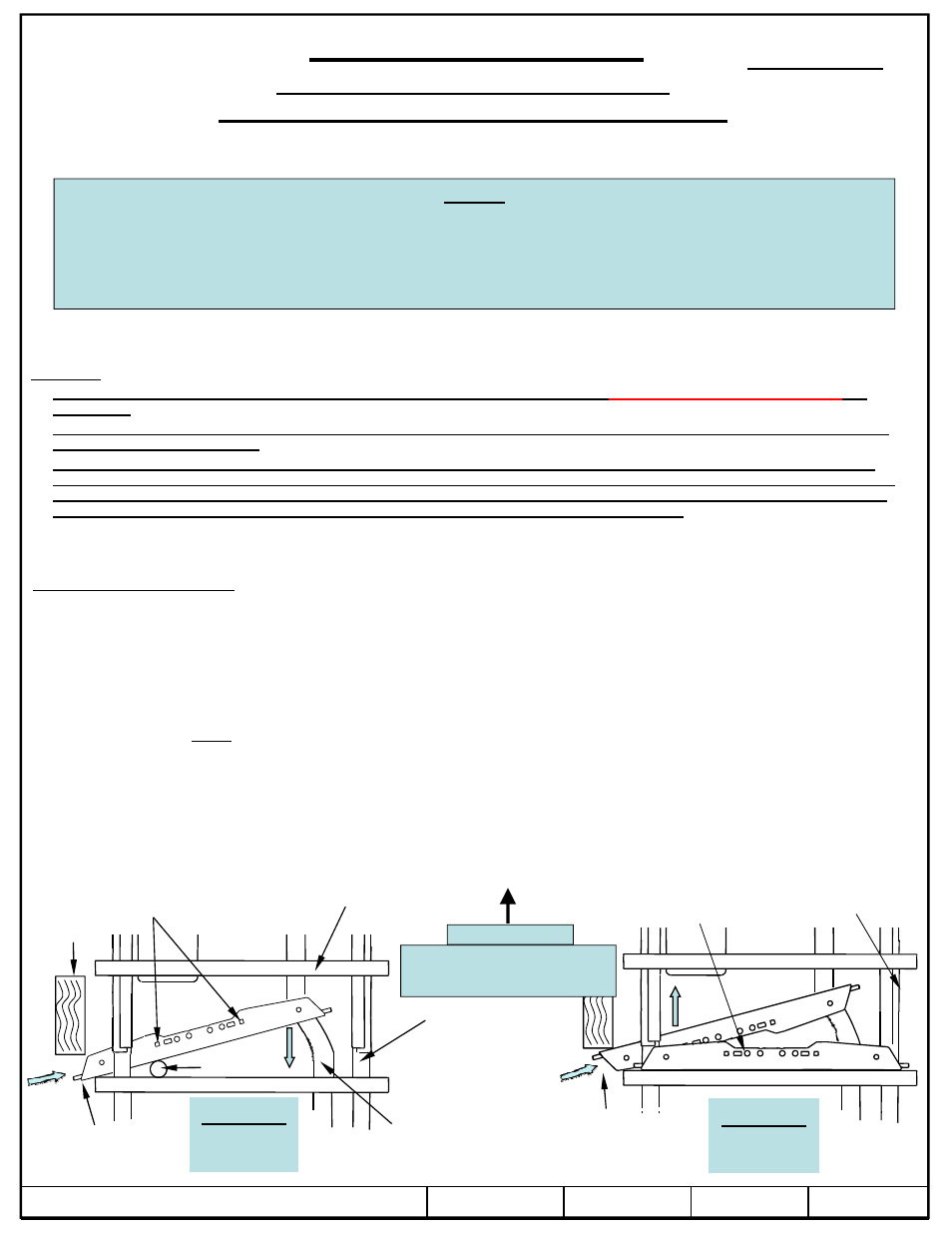
Vehicle Forward
Front bed
support
Exhaust
Passenger’s
side frame rail
Rear tire
Shock
Looking down from above
with truck bed hidden
Figure 2b.
Same view
as Page 2
Install rear
cross member first
Rear crossmember
in place
Install front
cross member second
May have to bend
vertical drip edge of
truck bed out slightly
Insert 5/8” carriage bolts in these square
slots and put a piece of tape across to
hold in position as you locate rail.
Typical both rails.
the rubber exhaust hangers from the exhaust hanger hooks. Lower or remove the spare tire to provide clearance for
the cross member installation. On 2010 and newer model year vehicles, temporarily remove the ground wire located
on the outside of the Driver’s side frame rail. It may make it easier to remove the spare tire heat shield also, use
10mm wrench or socket to remove (5) bolts and or nuts holding it in place.
2. Position the cross members from underneath: Place the rear cross member into position by inserting behind driver’s
side rear tire, in front of shock above spring beneath truck frame as shown in (Figure 2a). Make sure it’s facing the
right direction. Note: the cross members in this kit are the same, but they face different directions as shown in
(Figures 1 & 6.). It may help to locate carriage bolts in square slots and put a piece of tape across top of head to top
of rail. See note below. Slide the end up over the exhaust and the passenger’s side frame rail. Pull rear crossmember
back into position as shown in (Figure 2b). Insert front cross member into place at the same location behind the tire
in front of the shock beneath the driver’s side frame rail, (Figure 2a). It may be necessary to bend the passenger’s
side drip edge of the truck bed out slightly to allow rail to go in place.
Figure 2a.
Same view
as Page 2