Draw-Tite 30048 SQUARE TUBE SLIDER User Manual
Page 5
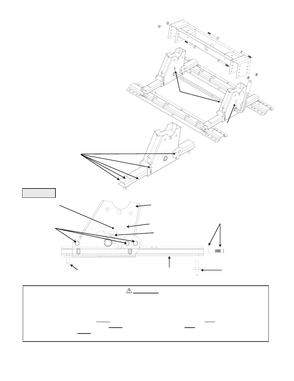
5. Loosely assemble head support to 5TH WHEEL
KWIK-SLIDE at desired height.
NOTE: Bottom position may not be used on all
hitch models.
Use 2 cotter pins provided to trap handle in place as shown.
Install indicator pin in handle as shown. Install such that the
indicator pin just goes through the bottom side of the handle.
(see figure 10).
ROLLERS
WELDED FOOT
LATCH
SLIDE TUBE
BOLT ON FOOT
figure 12
SLIDE UPRIGHT
LEAF SPRING
BOLT & LOCKWASHER
7. Coat top & side surfaces of slide tube and roller holes
(6 places) in each slider assembly with all purpose grease
or teflon lube, use as needed (see figure 11). Repeat this
application monthly during use.
figure 11
figure 10
6. Use a two step procedure to tighten hardware
A. Start at a point and snug all hardware.
Do not overlook connections under
bed at frame. Note sequence.
B. Using same start point and sequence, torque all hardware.
Torque 1/2” bolts to 85 lb.ft.
Cotter pins
Indicator pin
WARNING:
Kwik-Slide hitches that are not properly locked can suddenly move and kill you!
To avoid death or serious injury:
•Never place any part of body in truck bed or between truck and trailer unless the
following conditions are met :
•All trailer tires MUST be blocked in front and behind each tire, AND
•Trailer landing gear MUST be resting on firm ground, AND
•Truck MUST be stationary, in park, with emergency brake on!
•Always perform “push” or “pull test” by following instructions in this manual.
LATCH CAM
OPERATION
5
30048IN – 9-27-04E
PCN7358
©2001, 2002, 2004 TOWING PRODUCTS, INC.
Litho in USA