Draw-Tite 90885 PRODIGY P2 User Manual
Draw-Tite For the car
the E-E/H programming mode as follows:
• Enter Reverse Mode by pressing the Boost Button
for 5 seconds while the brake pedal is pressed until
[ .r ] displayed.
• While continuing to have the brake pedal pressed,
momentarily release the Boost Button for less than
one second and then press and continue to hold the
boost button down for an additional 5 seconds.
• The display will now change from the boost value
to a flashing
[ E. ] or [ E.H ]. Depress and release
Boost repeatedly to select the desired mode.
• Engage the Manual Knob to accept the mode, or
wait 10 seconds for the function to automatically
time out and accept the mode. The mode selected
will be stored in memory even when disconnected.
When in Electric over Hydraulic mode, the display
will change to
[ .C ] and [ n.C ]. The upper-case
“C” indicated E/H rather than the lower case “c” for
Electric mode.
(Réglage de la suralimentation – Suite)
Lorsque la suralimentation est au niveau 2,
[ b
.2
],
ou
lorsque la suralimentation est au niveau 3, [ b
.3
],
durant un événement de freinage, la puissance démarre
automatique-ment à environ 28 % du réglage de puis-
sance et elle augmente avec la décélération.
Quelques cas où l’utilisation du bouton de suralimenta-
tion pourrait être souhaitable :
• On veut que le freinage de la remorque « GUIDE »
le véhicule de remorquage.
• Remorquage à pleine charge par rapport au
remorquage à vide.
• Dégradation de la performance de freinage (la
majorité des freins électriques doivent être réglés
manuellement – voir l’annexe A ou consulter le
concessionnaire dans le cas d’un réglage ou d’une
réparation).
REMARQUE :
Le dispositif de suralimention
n’est pas conçu pour remplacer le réglage ou la
réparation des freins.
Consulter le tableau ci-dessous pour connaître les
réglages de suralimentation recommandés (identifiés par
un
X) en regard des relations typiques entre le poids de
la remorque et le poids du véhicule.
Sélectionner le réglage de la suralimentation en fonc-
tion des situations de remorquage particulières, des
préférences en matière de conduite et de l’état des freins
de la remorque.
Prodigy
®
P2
Commande électronique de frein
Pour applications de 2, 4, 6 et 8 freins
LISEZ CECI EN PREMIER :
Il importe de lire ou de suivre attentivement toutes
les consignes avant de poser ou d’utiliser la
commande de frein Prodigy P2. Ces consignes doi-
vent être conservées avec la commande de frein pour
consultation future.
Composants de la commande de frein
A. Bouton de puissance
B. Bouton de suralimentation
C. Bouton manuel
D. Connecteur (pour faisceau de fils)
E. Trou de montage (1 par côté)
Faits importants à garder en mémoire
1. Ne pas monter ni actionner des appareils produi-
sant des HF (téléphones cellulaires, radios bidirec-
tion nelles) à proximité (moins de 12 po) de la
commande de frein.
2. La commande de frein Prodigy P2 utilise un
capteur inertiel. Elle détecte la décélération et
produit une sortie basée sur la décélération, d’où
l’expression « freinage proportionnel ».
3. La commande de frein Prodigy P2
« RETIENDRA » la remorque avec 25% du
réglage de puissance à l’état statique avec la
pédale de frein enfoncée durant au moins 5 sec-
ondes.
4. La commande de frein Prodigy P2 actionnera les
freins proportionnellement en marche arrière.
Elle appliquera la tension électrique appropriée
en fonction de la décélération.
5. Pour assistance technique et informations concer-
nant la garantie, prière d’appeler le 1-888-785-
5832 ou www.tekonsha.com.
6. AVERTISSEMENT : Le poids nominal brut
combiné (PNBC) ne doit jamais dépasser le poids
recommandé par le fabricant du véhicule.
(Boost Setting continued)
[ b
.I
], during a braking event, the power automatically
starts out at approximately 14% of the power setting and
increases with deceleration. With the boost on level 2,
[ b
.2
], or with the boost on level 3, [ b
.3
], during
a braking event, the power automatically starts out at
approximately 28% of the power setting and increases
with deceleration.
Some cases where you might want to use the boost button:
• You like the trailer braking to ‘LEAD’ the tow
vehicle’s braking
• Towing a full vs. empty trailer
• Degraded brake performance (most electric brakes
require manual adjustment - see Appendix A or a
dealer for adjustment or repair)
NOTE:
Boost not intended to be used to take place of
trailer brake adjustment or repair.
See the chart below for recommended “Boost” settings
(indicated with
X) for typical Trailer to Vehicle weight
relationships.
Select your boost setting based on your towing situation,
driving preference and condition of your trailer brakes.
Installation Guide
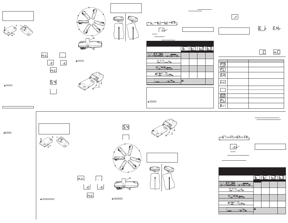
The Prodigy P2 can be mounted from 0 degrees to
360 degrees vertically in the direction of travel. (See
Diagram for Mounting the Prodigy P2).
Failure to install the Prodigy P2 within these con-
straints may cause impaired performance.
Wiring Brake Control
Your Prodigy P2 brake control has a unique
connector located at the back of the control. This
connector allows you two options to wire your brake
control.
Option 1:
Use Pigtail Wiring Harness included. This harness can
be installed by following the Generic Wiring Guide.
Option 2:
Use a vehicle specific wiring harness. If your vehicle
came with a factory tow package that included a 7-way
connector, you can purchase a Tekonsha OEM wiring
harness with the Prodigy P2 connector on one end and
your specific vehicle’s connector on the other.
Display Readings after Wiring the Prodigy P2
After successfully wiring your Prodigy P2 you should
see the following on the two-digit display:
• Power to Prodigy P2 without trailer connected.
• Power to Prodigy P2 with trailer connected and
• Manual Knob Activated without trailer
• Manual knob activated (with trailer), 5.4 denotes a
hypothetical power output. This value is set using
the power knob. Range is 0.0 to 13 volts. This is
an indication of voltage output to electric brakes.
• Power to Prodigy P2 but display is in power saving
mode (no motion or activity for at least fifteen
minutes).
Mounting the Prodigy P2
Traditional Bracket Mount
A. Mounting Bracket
B. #8 X 3/8" Machine Screw with Internal Tooth
Washer
1. CAUTION Drilling or use of longer screws may
damage unit.
2. Securely mount bracket to a solid surface.
3. Insert supplied #8 x 3/8" machine screws on each
side into the mounting holes.
4. Adjust control to desired position and tighten
screws
until snug.
Under Dash Pocket Mount
A. Pocket Mount
B. #6 X 1/2" Self Tapping Screws
1. Securely mount Pocket Mount to a solid surface
using supplied #6 X 1/2" Self Tapping Screws.
2. Insert Prodigy P2 Brake control.
3. Plug in connector.
NOTE:
1. Front of the Prodigy P2 must be horizontal (+_ 20
degrees), see below.
2. The Prodigy P2 must be parallel to direction of
travel (+_ 20 degrees), see below.
Automatic Leveling of the Sensor
The Prodigy P2 will automatically acquire the proper
level setting. It will also automatically adjust as you
travel up or down hills.
Adjusting the Power to the Trailer
Brakes
(Prior to setting Boost)
Once the control has been securely mounted in the
direction of travel, it is necessary to set the power
needed to stop the trailer during a braking event.
1. Connect trailer to tow vehicle.
2. With engine running hold manual full left and set
Power Knob to indicate approximately 6.0
3. Drive tow vehicle and trailer on a dry level paved
surface at 25 mph and fully apply manual knob.
3
If trailer brakes lock up:
q
Turn power down using power knob.
3
If braking was not sufficient:
q
Turn power up using power knob.
4. Repeat Step (3) until power has been set to a point
just below wheel lock up or at a sufficient force as
to achieve maximum braking power.
5. Using the brake pedal, make a few low speed
stops to check the power setting. Trailer braking
is initiated and terminated via the stoplight switch.
When the brake pedal is released, trailer braking
will cease.
360˚
0˚
Direction of Travel
Direction of Travel
Correct
Incorrect
P/N 120065-006
REV A
11/09
Reverse
When backing a trailer you can cancel “BOOST” and
“HOLD” for a period of three minutes. This can be
accomplished by pressing the boost button continu-
ously for five seconds with the brake pedal depressed.
The display will indicate:
(If “boost” was active, the right hand decimal point
will also be on.) After three minutes the “BOOST” and
“HOLD” features will automatically return to your
previous settings.
NOTE:
Returning to your previous settings prior to three min-
utes can be accomplished by pressing the boost button.
T y p i c a l B o o s t S e t t i n g s F o r O p t i m a l P e r f o r m a n c e
(with properly adjusted trailer brakes*)
Trailer WeighT compared to Vehicle WeighT
Trailer weighs
less than Vehicle
Trailer weighs
approximately same as Vehicle
Trailer weighs
up to 25% more than Vehicle
Trailer weighs
up to 40% more than Vehicle
Trailer weighs
oVer 40% more than Vehicle
X
X
X
X
X
X
X
X
X
X
X
WARNING
Do not exceed Gross
Combined Weight Rating (GCWR)
* increased Boost setting may be needed if trailer brakes are worn, see appendix a or a dealer for brake adjustment or repair.
INCREASING BOOST LEVEL
➮
BOOST “OFF”
Boost Setting
The boost button was designed to allow a more aggressive
setting for your trailer brakes and is available in three lev-
els -
[ b
.I
], [ b
.2
], [ b
.3
]. Each incremental boost setting
increases the sensitivity of the Prodigy P2’s inertial sen-
sor, enhancing the paticipation of the trailer brakes during
a braking event.
The first press on the boost button displays the current set-
ting. Boost is advanced to the next level by continuing to
press the boost button.
Five seconds after setting the boost level, the display will
show
indicating Boost On by the right most decimal.
For example: With the boost off,
[ b
.
], during a brak-
ing event, the power to the brakes starts out at zero and
increases with deceleration. With the boost on level 1,
Boost On
3. The power may need to be adjusted for different
load weights and road conditions.
4. Not all trailer brakes will lock up due to various
conditions. However, inability to lock up the
brakes generally indicates the need for an inspec-
tion to determine the cause.
5. When the power is set correctly you should
feel unified braking between the trailer and tow
vehicle.
NOTE:
1. Always warm the trailer’s brakes before
setting the power. Warm trailer brakes tend to
be more responsive than cold brakes. To warm
trailer brakes, drive a short distance (1/4 mile) at
45 MPH with manual lever engaged enough to
cause trailer braking at a low level.
2. WARNING The power should never be set
high enough to cause trailer brakes to lock up.
Skidding trailer wheels can cause loss of direc-
tional stability of trailer and tow vehicle.
Guide d’installation
Le Prodigy P2 peut se monter de 0 à 360 degrés ver-
ticalement dans la direction du déplacement. (Voir le
Schéma de montage du Prodigy P2).
Le défaut de poser la commande de frein Prodigy P2
à l’intérieur de ces contraintes peut altérer la
performance.
Câblage de la commande de frein
La commande de frein Prodigy P2 est dotée d’un
nouveau connecteur unique situé à l’arrière de la com-
mande. Ce connecteur est offert avec deux options pour
câbler la commande de frein.
Option 1:
Utiliser le faisceau de fils enroulés qui est inclus.
Ce faisceau peut être posé en consultant le guide de
câblage générique.
Option 2:
Utiliser le faisceau de fils spécifique de Ford, Dodge
ou GM. Si un ensemble de remorquage d’usine com-
prenant un connecteur à 7 voies était fourni avec votre
véhicule, vous pouvez acheter un faisceau de fils
OEM Tekonsha muni du connecteur Prodigy P2 à une
extrémité et du connecteur spécifique à votre véhicule à
l’autre extrémité.
Affichage des mesures après le câblage de la com-
mande Prodigy P2
Après avoir réussi le câblage de votre commande de
frein Prodigy P2, vous devriez apercevoir les éléments
suivants sur l’afficheur à deux chiffres :
• L’alimentation se rend à la commande Prodigy P2
et la remorque n’est pas attelée.
• Courant entre Prodigy P2 et la remorque branché et
• Le bouton manuel est activé et la remorque n’est
pas attelée.
• Le bouton manuel est activé (avec la remorque),
5.4 représente une puissance de sortie hypothé-
tique. Cette valeur est réglée à l’aide du bouton de
puissance. La fourchette de valeurs s’étend de 0.0
à 13 volts. Il s’agit d’une indication de la tesion de
sortie aux freins électriques.
• Courant à Prodigy P2, mais le cadran est en mode
économie (aucun mouvement ou activité pendant
au moins quinze minutes).
Montage de la commande de frein Prodigy P2
Montage traditionnel du support
A. Support de montage
B. Vis de mécanique No. 8 x 3/8 po avec rondelle à
crans intérieurs
1. ATTENTION : Le perçage ou l’utilisation de vis
plus longues peut endommager l’unité.
2. Monter solidement le support sur une surface
ferme.
3. Insérer les vis de mécanique No. 8 x 3/8 po dans
les trous de montage de chaque côté.
4. Régler la commande à la position désirée et serrer
les vis fermement mais non excessivement.
Montage dans un logement
sous le tableau de bord
A. Logement
B. Vis autotaraudeuse No. 6 x 1/2 po
1. Monter solidement le logement sur une surface
solide à l’aide des vis autotaraudeuses No. 6 x 1/2
po.
2. Insérer la commande de frein Prodigy P2.
3. Brancher le connecteur.
REMARQUE :
1. Le devant de la commande de frein Prodigy P2
doit être horizontal (+_ 20 degrés), voir ci-après.
2. La commande de frein Prodigy P2 doit être parallèle
au sens de marche (+_ 20 degrés), voir ci-après.
Mise à niveau automatique du capteur
La mise à niveau de la commande de frein Prodigy P2
s’effectuera automatiquement de la manière appropriée.
La mise à niveau s’ajustera aussi automatiquement
lorsque vous circulerez sur un terrain accidenté.
Sens de marche
Sens de marche
Correct
Incorrect
Réglage de la suralimentation
Le bouton de suralimentation a été conçu dans le but de
permettre un réglage plus agressif des freins de la
remorque et il est disponible selon trois niveaux -
[ b
.I
],
[ b
.2
], [ b
.3
]. Chaque augmentation du réglage de la
suralimentation accroît la sensibilité du capteur inertiel,
intensifiant ainsi la participation des freins de la
remorque lors d’un événement de freinage.
La première pression sur le bouton de suralimentation
montre le réglage actuel. La suralimentation passe au
niveau suivant quand on continue à presser sur le bouton
de suralimentation.
Cinq secondes après le réglage du niveau de suralimenta-
tion,
l’affichage indiquera Boost On (alimentation ouverte)
en allumant la décimale située à l’extrême droite.
Par exemple : Lorsque la suralimentation est fermée
[ b
.
] durant un événement de freinage, la puissance aux
freins démarre à zéro et elle augmente avec la décéléra-
tion. Lorsque la suralimentation est au niveau 1 durant
un
[ b
.I
] événement de freinage, la puissance
démarre automatiquement à environ 14 % du réglage de
puissance et elle augmente avec la décélération.
Boost On
alimentation
ouverte
Réglage de la puissance aux freins
de la remorque
(Avant le réglage de la sur-
alimentation)
Une fois la commande fermement montée dans la
direction du déplacement, il faut régler l’alimentation
électrique nécessaire pour arrêter la remorque lors d’un
événement de freinage.
1. Raccorder la remorque au véhicule de remor-
quage.
2. Le moteur en marche, maintenir le bouton Manual
(manuel) à l’extrême gauche et régler le bouton de
puissance de façon à indiquer environ 6.0.
3. Conduisez le véhicule de remorquage et la
remorque sur une surface asphaltée horizontale
sèche à 40 km/h et mettez complètement la poi-
gnée manuelle.
3
Si les freins de la remorque se verrouillent :
q
Réduire la puissance à l’aide du bouton de puis-
sance.
3
Si le freinage n’était pas suffisant :
q
Augmenter la puissance à l’aide du bouton de
puissance.
4. Répéter l’étape (3) jusqu’à ce que la puissance ait
été réglée à un point tout juste sous le verrouillage
des roues ou à une force suffisante de manière à
obtenir une puissance de freinage maximale.
5. En utilisant la pédale de frein, faire quelques
arrêts à basse vitesse pour vérifier les réglages de
puissance. Le freinage de la remorque s’amorce
et se termine par le biais de l’interrupteur de feu
d’arrêt. Lorsque la pédale de frein est relâchée, le
freinage de la remorque cesse.
* un réglage de suralimentation plus élevé peut s’avérer nécessaire si les freins de la remorque sont
usés ; consulter l’annexe a ou le concessionnaire concernant le réglage ou la réparation des freins.
POiDS De la reMOrQUe comparé au
POiDS DU VÉhicUle
Le poids de la remorque est
inférieur à celui du véhicule
Le poids de la remorque est
approximatiVement égal
à celui du véhicule
Le poids de la remorque est
jusqu’à 25 % supérieur
à celui du véhicule
Le poids de la remorque est
jusqu’à 40 % supérieur
à celui du véhicule
Le poids de la remorque est
plus de 40 % supérieur
à celui du véhicule
X
X
X
X
X
X
X
X
X
X
X
NIVEAU DE SURALIMENTATION CROISSANT
AVERTISSEMENT :
Ne pas dépasser le poids
nominal brut combiné (PNBC)
R é g l a g e t y p i q u e d e l a s u r a l i m e n t a t i o n p o u r
u n e p e r f o r m a n c e o p t i m a l e
(avec des freins de remorque correctement réglés*)
SUraliMeNTaTiON
« FerMÉe »
Prodigy
®
P2
Electronic Brake Control
For 2, 4, 6 and 8 brake applications
READ THIS FIRST:
Read and follow all instructions carefully before
installing or operating the Prodigy P2. Keep these
instructions with the Brake Control for future
reference.
Components of the Brake Control
A. Power Knob
B. Boost Button
C. Manual Knob
D. Connector (For Wiring Harness)
E. Mounting Hole (1 per side)
Important Facts to Remember
1. Do not mount or activate RF generating items
(cell phones, two way radios) near (less than 12")
the brake control.
2. The Prodigy P2 employs an inertial sensor. It
senses deceleration and generates an output that is
based on deceleration, thus the term “Proportional
Braking”.
3. The Prodigy P2 will “HOLD” your trailer with
25% of power setting while you are at a standstill
with brake pedal applied for longer than 5 sec-
onds.
4. The Prodigy P2 will brake proportionally in
reverse. It will apply the appropriate brake voltage
based on deceleration.
5. For Technical Assistance and Warranty
Information call: 1-888-785-5832 or
www.tekonsha.com.
6. WARNING The Gross Combined Weight Rating
(GCWR) must never exceed the vehicle manufac-
turers recommendation.
Displays for 15
seconds then
changes to:
Boost
feature
engaged.
Boost
feature not
engaged.
Inscrit pendant
15 secondes, puis
change en:
Suraliment-
ation enga-
gée.
Suraliment-
ation non
engagée.
(Blank
Display)
(affichage
Vide)
➮
➮
➮
Display
Situation
Probable Cause
Troubleshooting Chart
Flashes 2 times a second or a
Trailer is connected and Prodigy P2 loses
steady display.
connection to battery ground.
Flashes 2 times per second.
Prodigy P2 “sees” an overload condition during
operation.
Flashes 2 times per second.
1. Brake wire sees short during idle condition.
2. Use of some test lights or non-Tekonsha testers
can cause this problem.
Flashes for 15 seconds
1. Trailer not connected to tow vehicle.
2. Trailer connected with open circuit on brake line.
3. Trailer connector disconnected or corroded.
4. Loss of trailer brake magnet ground.
No display with manual or pedal
1. Loss of power to Prodigy P2.
activation.
2. Loss of ground to Prodigy P2.
No display until activation
Prodigy P2 is in power-saving mode due to no motion
for 15 minutes.
No braking.
Power control set to 0.
Flashes 2 times per second.
Power interruption while brake
pedal is depressed.
Error
Brake Control is inoperative. Call technical service for
return.
(Blank
Display)
Electric Over Hydraulic Mode
The Prodigy P2 will support most customer supplied
electric over hydraulic braking systems.
An electric over hydraulic system is a system where
the Brake Control’s output is used to drive a customer
supplied electric over hydraulic braking system. The
customer will determine which electric over hydraulic
system is suitable for their application.
The Prodigy P2 can be switched between Electric (E)
and Electric over Hydraulic (E/H) modes by entering
Boost On
electric Mode
(Flashing)
(Flashing)
electric/hydraulic Mode
Boost On
(Appendix A: Trailer Brake Adjustment continued on next column)
Appendix A: Trailer Brake Adjustment**
Brakes should be adjusted after the first 200 miles of
operation when the brake shoes and drums have “seated” and
at 3000 mile intervals, or as use and performance requires. The
brakes should be adjusted in the following manner:
1. Jack up trailer and secure on adequate capacity jack
stands. Follow trailer manufacturers recommendations for
lifting and supporting the unit. Check that the wheel and
drum rotate freely.
WARNING Do not lift or support trailer on any part of
the axle or the suspension system.
2. Remove the adjusting hole cover from the adjusting slot
on the bottom of the brake backing plate.
3. With a screwdriver or standard adjusting tool, rotate the
starwheel of the adjuster assembly to expand the brake
shoes. Adjust the brake shoes out until the pressure of the
linings against the drum makes the wheel very difficult to
turn.
Note: With drop spindle axles, a modified adjusting tool with
about an 80 degree angle should be used.
4. Then rotate the starwheel in the opposite direction until
the wheel turns freely with a slight lining drag.
5. Replace the adjusting hole cover and lower the wheel to
the ground.
6. Repeat the above procedure on all brakes.
WARNING Never crawl under your trailer unless it is
resting on properly placed jack stands.
Follow the trailer manufacturers recommendations for lifting
and supporting the unit. Do not lift or place supports on any
part of the suspension system.
**Note: Trailer Brake Adjustment procedures courtesy Dexter
Axle.
(Electric Over Hydraulic continued)
360˚
0˚
(Flashing)
Trailer connected
Trailer Not connected
electric/hydraulic Mode
©2009 Cequent Performance Products