Draw-Tite 24788 SPORTFRAME HITCH User Manual
Installation instructions, Nissan altima, maxima, Part numbers
Tighten all 1/2” fasteners with torque wrench to 75 Lb.-Ft. (102N*M)
Note: check hitch frequently, making sure all fasteners and ball are properly tightened. If hitch is removed, plug all holes in trunk pan or other body panels to
prevent entry of water and exhaust fumes. A hitch or ball which has been damaged should be removed and replaced. Observe safety precautions when working
beneath a vehicle and wear eye protection. Do not cut access or attachment holes with a torch.
This product complies with safety specifications and requirements for connecting devices and towing systems of the state of New York, V.E.S.C. Regulation V-5
and SAE J684.
Installation Instructions
Nissan Altima, Maxima
Part Numbers:
60944
24788
77162
Wiring Access Location: PC3,4
Equipment Required: Metal Shears, File, Paint
Wrenches: 9/16”, 11/16”, 3/4”
Drill Bits: -
1) Remove spare tire from trunk.
2) In floor of trunk pan, remove rubber plug from front drain hole. Puncture bonded covering from rear drain hole.
3) Lower exhaust by removing hanger bracket/brackets from end of muffler/mufflers.
4) Remove plastic rivets from supports on bottom edge of bumper fascia. Rivets are released by first pulling out centre post of rivet approx 1/4”. Rivet can then be
pushed out by hand.
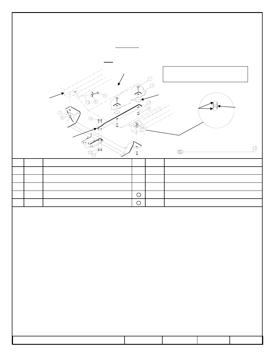
5) Referring to illustration, remove material from between adjacent holes in frame member using metal shears. Dress sides of hole with file and enlarge opening to
allow passage of head of 7/16” carriage bolt (5). Refer to “ Access To Enclosed Frame”. BE SURE TO COVER ANY CUT/BARE METAL SURFACES WITH A
RUST INHIBITOR. Repeat for other side of vehicle.
6) Thread bolt leader (12) onto carriage bolt (5) and insert other end of bolt leader through hole in reinforcing plate (6). Fish bolt leader and assembly through
access hole in frame member (produced in step 5) and out through proper bolt hole. Carefully pull through hole until bolt is into position. Remove bolt leader. Repeat
for other side.
7) Raise hitch up to frame while holding plastic fascia support fingers back to allow hitch crosstube to fit up into cavity behind bumper.
8) Being careful not to push bolts back into frame, lift hitch into position. Install Washers and nuts (7&8) a few threads, holding hitch, but allowing it to hang loosely.
9) Attach trunk strap to top surface of mounting tab on hitch receiver using 3/8” carriage bolts (9), washers (10) and nuts (11).
10) Using silicone compound to ensure air tight seal, install trunk plates (2) length ways with vehicle (long side running front to back). Pass 1/2” carriage bolts (1)
through trunk plates from above, through drain holes in trunk pan and through holes in trunk strap. Install washers and nuts (3&4).
12) Adjust trunk plates, trunk strap and hitch, tighten all bolts, refer to torque table on the instruction sheet.
13) Re-attach bumper fascia using plastic rivets removed in step 4.
14) Raise exhaust and re-attach muffler hanger bracket/brackets.
15) Replace spare tire.
Tighten all 7/16 fasteners with torque wrench to 50 Lb.-Ft. (68N*M)
Rev. B
10-31-06
24788N
Sheet 1 of 4
z
2006 Cequent Towing Products
Nut – 3/8”-16
Qty. (2)
Carriage Bolt – 7/16” -14 x 1-1/4” GR. 5
Qty. (2)
5
Bolt Leader – 7/16
Qty. (1)
Bolt Block – 1” x 3” x 1/4”
Qty. (2)
6
Washer Conical Toothed - 3/8”
Qty. (2)
Nut – 1/2”-13
Qty. (2)
4
Carriage Bolt – 3/8”-16 x 1-1/4” GR. 5
Qty. (2)
9
Washer Conical Toothed – 1/2”
Qty. (2)
3
Nut – 7/16” x 14
Qty. (2)
8
Bolt Block – 2” x 2-1/2” x 1/4”
Qty. (2)
2
Washer Conical Toothed – 7/16”
Qty. (2)
7
Carriage Bolt – 1/2”-13 x 1-1/2” GR. 5
Qty. (2)
1
2000 LB (908 Kg) Max Gross Trailer Weight
200 LB (91 Kg) Max Tongue Weight
Do Not Exceed Lower of Towing Vehicle
Manufacturer’s Rating or
Drawbar must be used in the
RISE position only.
Drawbar Kit:
3597
Fastener Kit: KA-8001-026
11
12
Tighten all 3/8” fasteners with torque wrench to 30 Lb.-Ft. (41N*M)
EXISTING
HOLES
REMOVE
MATERIAL
HERE
ENLARGE AS
REQUIRED
ACCESS TO ENCLOSED FRAME
EXISTING DRAIN HOLE
TRUNK PAN –
SPARE TIRE WELL
~
FRAME
TRUNK STRAP
Form F206 Rev A 5605