Draw-Tite 24909 SPORTFRAME HITCH User Manual
Installation instructions, Part numbers
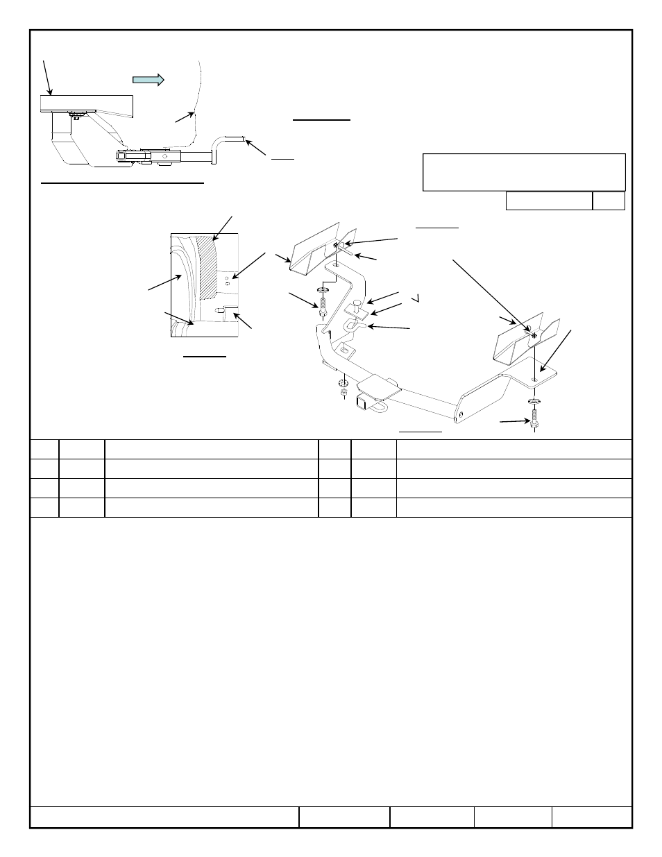
Installation Instructions
NISSAN VERSA NOTE
Part Numbers:
24909
60340
77296
29175 UH
Hitch Shown In Proper Position
Equipment Required: Galvanic
isolators (provided), lubricant
or soapy water, tin snips,
Wrenches: M10, 11/16, & 3/4
Drill Bits: 1” hole saw
*Drivers side only
1.
Lower exhaust at the rubber isolator. Spraying a lubricant or soapy water on the metal hanger rod and the rubber isolator helps removal.
2.
Remove rearward m6 bolt holding heat shield in place. Return to owner. Trim heat shield for access to hole on passenger frame rail. Fig 3
3.
Remove the black box (charcoal canister ) from frame by removing M8 bolt and sliding the box forward.
4.
Using 1” hole saw, drill a access hole into side of driver and passenger side frame rail inline with the existing hole to insert handle nut. Fig 2
5.
Install ½” handle nuts into frame thru drilled holes.
6.
Install the ½ carriage bolt and spacer as shown in Fig 1., to the tie down hook.
7.
Apply the clear galvanic isolators to the passenger side bracket as shown. Fig 1
8.
Raise the hitch into position and install conical washer and nut to tie down attachment, do not tighten down at this point. Fig 1.
9.
Feed the 1/2 fasteners through slots on both sides and install fasteners as shown Fig 1. Note: on passenger side sandwich the heat shield between the frame
rail and the hitch.
10.
Center the hitch on the vehicle.
11.
Torque all fasteners to specifications shown below.
12.
Reinstall exhaust.
©
2013 Cequent Performance Products, Inc
Sheet 1 of 3
24909N
04-15-2014
Rev. C
1
1
1
1
Qty. (1)
Carriage bolt ½-13 X 2.00 GR5
5
5
5
5
Qty. (2)
HANDLE NUT ½ -13
2
2
2
2
Qty. (1)
Spacer ¼” x 1.50 x 3.00
6
6
6
6
Qty. (2)
BOLT ½ -13
3
3
3
3
Qty. (3)
Conical washer ½”
7
7
7
7
Qty. (2)
GALVANIC ISOLATOR
4
4
4
4
Qty. (1)
Hex nut ½-13
Note: check hitch frequently, making sure all fasteners and ball are properly tightened. If hitch is removed, plug all holes in trunk pan or other body panels to prevent entry of water and
exhaust fumes. A hitch or ball which has been damaged should be removed and replaced. Observe safety precautions when working beneath a vehicle and wear eye protection. Do not cut
access or attachment holes with a torch.
This product complies with safety specifications and requirements for connecting devices and towing systems of the state of New York, V.E.S.C. Regulation V-5 and SAE J684.
Fastener Kit: 24909F
Do Not Exceed Lower of Towing Vehicle
Manufacturer’s Rating or
Wiring Access Location: PC3, 4
Form: F205 Rev A 5-6-05
Tighten all ½-13 GR5 fasteners that use a handle nut with torque wrench to 50 Lb.-Ft. (68 N*M)
Tighten all ½-13 GR5 fasteners with torque wrench to 75 Lb.-Ft. (102 N*M)
Drawbar must be used in the
RISE position only.
Drawbar Kit:
3592
2000 LB (908 Kg) Max Gross Trailer Weight
200 LB (90.8 Kg) Max Tongue Weight
Figure 2
Figure 1
Figure 3
Trim heat shield as
shown
.
Trim heat shield as shown.
Access hole under heat
shield passenger side only
Frame
rail
Muffler
Rubber
isolator
Tie down hook
1
3
2
4
6
3
7
Frame rail
Fascia
Tail pipe
Exhaust & heat
shield not shown
Rearward
Galvanic
isolators
between
heat shield
and hitch
bracket
6
Drill access hole for
handle nut.
3
5
5
Accessory Rating
A
Made in Mexico