Draw-Tite 24830 SPORTFRAME HITCH User Manual
Installation instructions, Audi a4 sedan, Part numbers
Installation Instructions
Audi A4 Sedan
Part Numbers:
77203
24830
60219
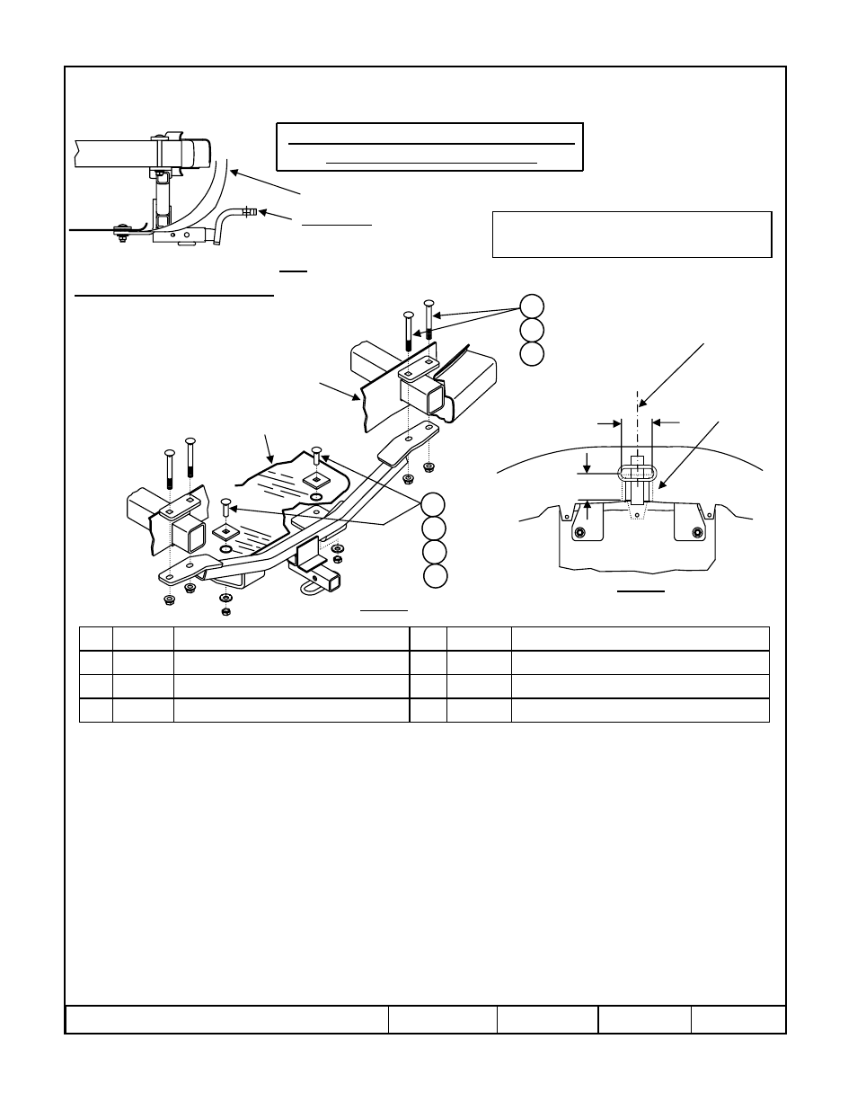
Hitch Shown In Proper Position
Wiring Access Location: PC1, PC2
Equipment Required: Utility Knife, Phillips screwdriver
Wrenches: ¾”
Drill Bits: N/A
1.
Remove the three (3) screws holding the plastic bumper fascia to the bottom of the trunk pan.
2.
Remove the spare tire and jack from inside trunk.
3.
Remove the two (2) rearmost plastic drain plugs from the bottom of trunk pan.
4.
Cut a notch in the lower part of the plastic fascia, approximately 3-1/4” wide x 3” deep, centered on vehicle, as shown in figure 2.
Obtain vehicle owner’s permission before cutting plastic fascia.
5.
Gently pull fascia down and rearward, and install the Top Plates and 4.50 long carriage bolts on top of the bumper support tubes.
6.
Raise hitch into position, aligning the slots in hitch brackets with long carriage bolts and loosely install the flanged locknuts onto carriage
bolts.
7.
Install the 1.75 long carriage bolts, spacer blocks, conical toothed washers, and hex nuts from inside of trunk pan and through holes in
forward hitch brackets.
8.
Tighten all 4.50 long Gr2 carriage bolts with torque wrench to 50 Lb.-Ft. (68 N*M)
9.
Tighten all ½-13 GR5 fasteners with torque wrench to 75 Lb.-Ft. (102 N*M)
10.
Re-install the two outer screws through bumper fascia and into the trunk pan.
11.
Re-install the jack and spare tire into trunk.
Rev. A
10-29-08
24830N
Sheet 1 of 3
z
2008 Cequent Towing Products
Hex nut, 1/2-13
Qty. (2)
7
Flanged Lock Nut, ½-13
Qty. (4)
3
Carriage Bolt ½-13 x 1.75 Gr5
Qty. (2)
4
Conical toothed washer, 1/2
Qty. (2)
6
Top Plate, 2.00 x 4.50 w/Square holes
Qty. (2)
2
Spacer Block, ¼ x 2 x 2
Qty. (2)
5
Carriage Bolt ½-13 x 4.50 Gr2
Qty. (4)
1
Note: check hitch frequently, making sure all fasteners and ball are properly tightened. If hitch is removed, plug all holes in trunk pan or other body panels to
prevent entry of water and exhaust fumes. A hitch or ball which has been damaged should be removed and replaced. Observe safety precautions when working
beneath a vehicle and wear eye protection. Do not cut access or attachment holes with a torch.
This product complies with safety specifications and requirements for connecting devices and towing systems of the state of New York, V.E.S.C. Regulation V-5
and SAE J684.
2000 LB (908 Kg.) Max Gross Trailer Weight
200 LB (90.8) Max Tongue Weight
Do Not Exceed Lower of Towing Vehicle
Manufacturer’s Rating or
Drawbar must be used in the
RISE position only.
Drawbar Kit:
3593
Fastener Kit: 24830F
Form F206 Rev A 5605
Plastic Fascia
Figure 2
Fascia Trim Detail
Bottom View
Fascia to
Be Trimmed
Fascia trimming required. Obtain vehicle
owner approval before cutting.
Figure 1
Trunk Pan
End Panel
1
2
3
4
5
6
7
Centerline
Of Vehicle
3-1/4”
3”