Draw-Tite 24836 SPORTFRAME HITCH User Manual
Installation instructions, Audi a6, Part numbers
Installation Instructions
Audi A6
Part Numbers:
60238
24836
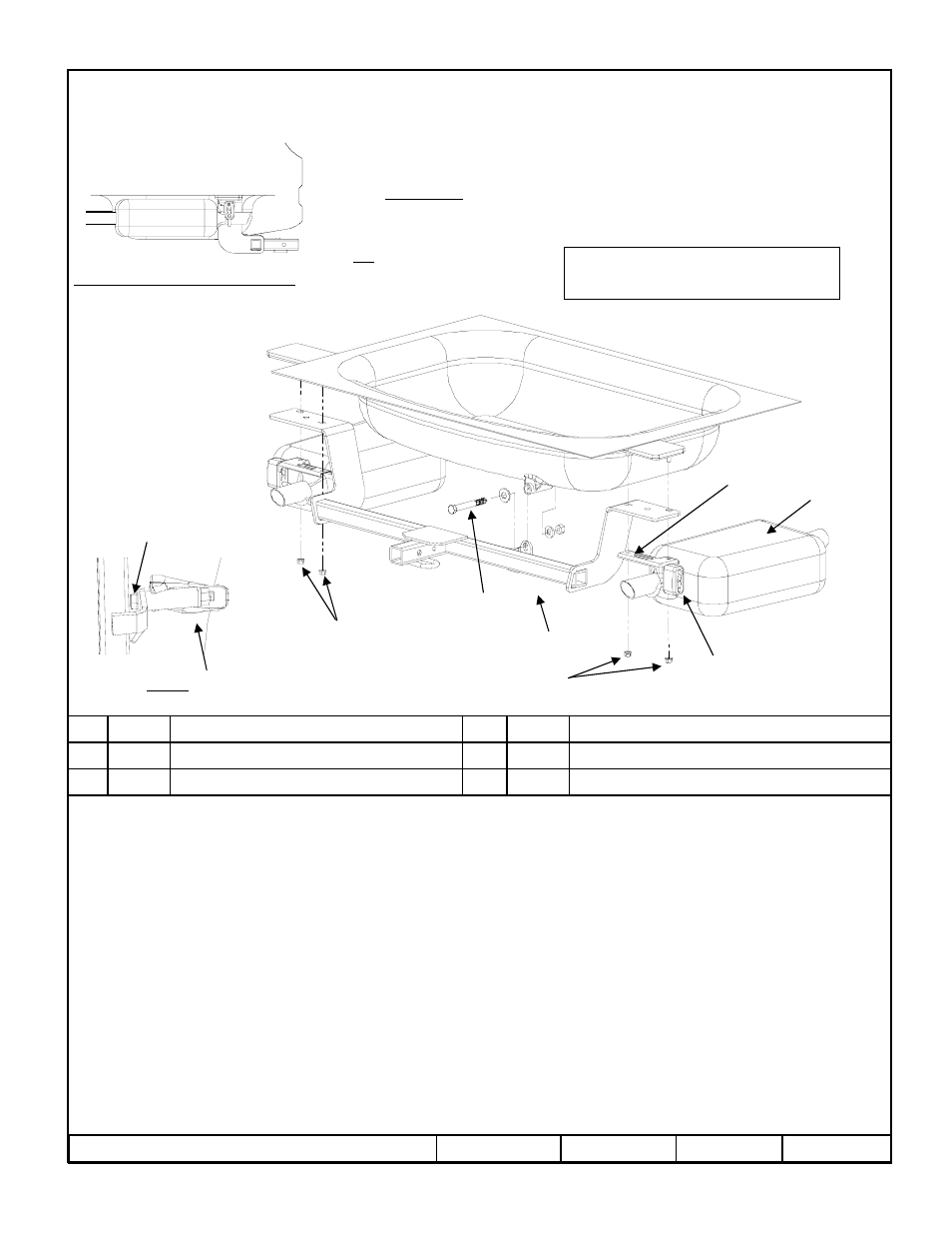
Hitch Shown In Proper Position
Wiring Access Location: PC1, PC2
Equipment Required: ¾” crow foot
Wrenches: m13, 3/4”
Drill Bits: none
1.
Raise vehicle on ramps or hoist.
2.
Remove existing m8 nuts from exhaust hangers.
3.
Lift passenger side of hitch over muffler, forward of exhaust hanger.
4.
By gently pulling down on the driver’s side muffler, slide the driver’s side of hitch over the tail pipe and forward into position.
5.
Hitch will be mounted between heat shield and muffler exhaust hangers using existing studs.
6.
With hitch in place, raise exhaust hangers back on their studs and start the m8 nuts (keep loose for now).
7.
Place 1/2” conical washer in place then install 1/2” bolt.
8.
Install 1/2” flat washer and nut.
9.
Tighten m8 nuts and then the 1/2” fastener with torque wrench.
Tighten all M8 fasteners with torque wrench to 25 Lb.-Ft. (34 n*m)
Rev. A
1-30-09
24836N
Sheet 1 of 3
z
2009 Cequent Towing Products
NUT - M8 X1.25 FLANGED LOCKING
Qty. (4)
5
CONICAL WASHER – 1/2”
Qty. (1)
2
WASHER – HARDEN FLAT
Qty. (1)
3
NUT - 1/2”-13
Qty. (1)
4
BOLT – HEX HEAD – 1/2”-13 X 4” LONG
Qty. (1)
1
Tighten all 1/2” fasteners with torque wrench 75 Lb.-Ft. (102 n*m)
Note: check hitch frequently, making sure all fasteners and ball are properly tightened. If hitch is removed, plug all holes in trunk pan or other body panels to
prevent entry of water and exhaust fumes. A hitch or ball which has been damaged should be removed and replaced. Observe safety precautions when working
beneath a vehicle and wear eye protection. Do not cut access or attachment holes with a torch.
This product complies with safety specifications and requirements for connecting devices and towing systems of the state of New York, V.E.S.C. Regulation V-5
and SAE J684.
2000 LB (908 Kg.) Max Gross Trailer Weight
200 LB (90.8 Kg.) Max Tongue Weight
Do Not Exceed Lower of Towing Vehicle
Manufacturer’s Rating or
Drawbar must be used in the
rise position only.
Drawbar Kit:
3593
Fastener Kit: 24836F
Form F206 Rev A 5605
View A
View A
1
2
3
4
USE 3/4” CROW FOOT
TO TORQUE BOLT
MUFFLER
EHXUAST HANGER
RUBBER
ISOLATOR
TRUNK
PAN
5
5