Draw-Tite 24894 SPORTFRAME HITCH User Manual
Installation instructions, Chevy spark 2lt, Part numbers
Installation Instructions
Chevy Spark 2LT
Part Numbers:
24894
60313
77282
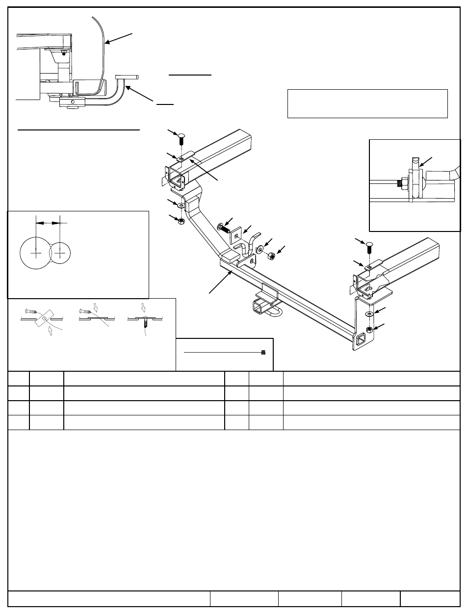
Hitch Shown In Proper Position
Wiring Access Location: PC3, PC4
Equipment Required: 7/16” Pull Wire
Wrenches: 11/16”, 7/8”
Drill Bits: 1/2”
1.
Lower the exhaust by removing the rubber exhaust isolator located above the muffler.
2.
Use 1/2” drill to enlarge the existing 3/4” holes on both frame rails as shown in Figure 1.
3.
Install 7/16” carriage bolts and 7/8” blocks using the reverse pull wire procedure shown in Figure 2. Leave pull wires attached.
4.
Raise hitch into position and feed pull wires through the holes on the hitch brackets.
5.
Install the 1/2” carriage bolt and 2” x 2” spacer to tie down hook as shown in Figures 3 & 4. Do not tighten down at this point.
6.
Feed the 7/16” carriage bolts though the holes on the hitch brackets, remove pull wires, and install fasteners as shown in Figure 3.
7.
Center the hitch on the vehicle and torque all fasteners to the specifications shown below.
8.
Reinstall exhaust.
z
2012 Cequent Performance Products, Inc.
Sheet 1 of 3
24894N
8-6-12
Rev. A
j
Qty. (2)
7/16”-14 x 1.50” Carriage Bolt GR.5
n
Qty. (1)
1/2”-13 x 1.75” Carriage Bolt GR.5
k
Qty. (2)
3” x 7/8” Block
o
Qty. (1)
2” x 2” Spacer
l
Qty. (2)
7/16” Conical Washer
p
Qty. (1)
1/2” Conical Washer
m
Qty. (2)
7/16”-14 Hex Nut GR. 2
q
Qty. (1)
1/2”-13 Hex Nut GR. 2
Tighten all 1/2”-13 fasteners with torque wrench to 75 Lb.-Ft (102 N-M).
Note: check hitch frequently, making sure all fasteners and ball are properly tightened. If hitch is removed, plug all holes in trunk pan or other body panels to
prevent entry of water and exhaust fumes. A hitch or ball which has been damaged should be removed and replaced. Observe safety precautions when working
beneath a vehicle and wear eye protection. Do not cut access or attachment holes with a torch.
This product complies with safety specifications and requirements for connecting devices and towing systems of the state of New York, V.E.S.C. Regulation V-5
and SAE J684.
Do Not Exceed Lower of Towing Vehicle
Manufacturer’s Rating or
Drawbar must be used in the
RISE position only.
Fastener Kit: 24894F
Fascia
2000 LB (908 Kg) Max Gross Trailer Weight
200 LB (90.8 Kg) Max Tongue Weight
Tighten all 7/16” fasteners with torque wrench to 50 Lb.-Ft (68 N-M).
A. Insert bolt and
Block into frame
B. Align block on
access hole
C. Pull bolt thru
block
Figure 2: Pull Wire Procedure
Figure 1: Access hole modification to allow
pull wiring of block and carriage bolt
0.563 (14.30 mm)
k
o
j
n
l
k
j
l
m
m
p
q
Tie down hook
Note: Orientation of Block
Figure 4: Back view of
properly Fastened
To Tie Down Hook
Drawbar Kit:
3594
Note: Drill rearward
of existing 3/4”
diameter hole
in frame rail
Figure 3: Hitch Installation
Tie down hook
Hitch
Pull Wire