Draw-Tite 36523 FRAME HITCH User Manual
Installation instructions, Subaru forester, Part numbers
Installation Instructions
Subaru Forester
Part Numbers:
90228
36523
06155
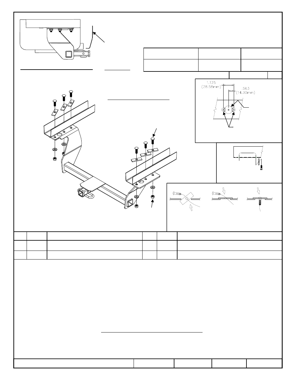
Hitch Shown In Proper Position
Wiring Access Location: SUV8
Equipment Required: Metal File
Wrenches: ¾”, 10mm
Drill Bits: 3/8”
1.
Lower exhaust by disconnecting rubber exhaust hanger(s) from hanger bracket(s).
2.
Remove (4) heat shield screws from the frame rail and set aside.
Note: When hitch is installed, heat shield will need to be discarded or trimmed to fit in position.
3.
Remove (3) plastic plugs from existing holes in each frame rail and discard.
4.
Use 3/8” drill and file to modify center hole in each frame rail, as shown in Figure 2, to allow fishwiring of spacers and carriage bolts.
5.
Fishwire spacers and 1/2” carriage bolts thru access hole modified in Step 4 and down thru holes in both frame rails (see figure 3), making sure
blocks span both sides of hole (see Figure 4) and are not overlapping one another.
6.
Raise hitch into position, being careful not to push fasteners into frame, and secure with conical washers and nuts.
7.
Reinstall heat shield and fasteners removed in Step 2.
8.
Raise exhaust back into position and reinstall exhaust hangers disconnected in Step 1.
z
2013 Cequent Performance Products, Inc. – Printed in Mexico
Sheet 1 of 3
36523N
4/15/14
Rev. B
1
1
1
1
Qty. (6)
Carriage Bolt – ½-13 x 1.75 GR5
4
4
4
4
Qty. (6)
Hex Nut – ½-13
2
2
2
2
Qty. (6)
Spacer–¼ x 1 x 3 (Square hole for ½” Carriage
Bolt)
5
5
5
5
Qty. (6)
Pull Wire – 1/2”
3
3
3
3
Qty. (6)
Conical Washer – 1/2”
Note: check hitch frequently, making sure all fasteners and ball are properly tightened. If hitch is removed, plug all holes in trunk pan or other body panels to prevent
entry of water and exhaust fumes. A hitch or ball which has been damaged should be removed and replaced. Observe safety precautions when working beneath a
vehicle and wear eye protection. Do not cut access or attachment holes with a torch.
This product complies with safety specifications and requirements for connecting devices and towing systems of the state of New York, V.E.S.C. Regulation V-5 and
SAE J684.
Do Not Exceed Lower of Towing Vehicle
Manufacturer’s Rating or
Fastener Kit: 36523F
Form F206 Rev A 5605
Figure 2: Access hole modification to allow
Fishwiring of block and carriage bolt.
Figure 3: Kink pull wire to keep
Spacer independent of bolt
3/8” Dia. Drilled holes
Existing 3/4”
Diameter hole
in frame
B. Align block on
access hole
A. Insert bolt and
Block into frame
C. Pull bolt thru
block
Figure 4: Fishwiring Procedure
Figure 1
Hitch type
Max Gross
Trailer WT (LB)
Max Tongue
WT (LB)
Weight Carrying
Ball Mount
3500 (1589 Kg)
300 (136 Kg)
Accessory Rating
B
Drawbar Kit:
36053
Tighten ½-13 GR5 fasteners to 75 lb.-ft. (102 N*M)
Fasteners Typical Both Sides
1
1
1
1
2
2
2
2
3
3
3
3
4
4
4
4
Fascia