Draw-Tite 36466 FRAME HITCH User Manual
Installation instructions, Volvo s-80, Part numbers
Installation Instructions
Volvo S-80
Part Numbers:
90171
36466
06608
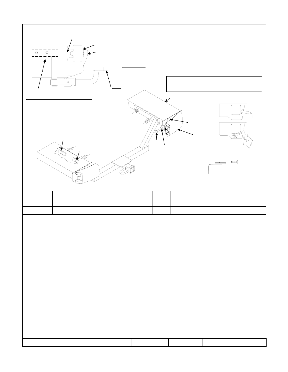
Hitch Shown In Proper Position
Wiring Access Location: PC3, 4
Equipment Required:
Wrenches: 11/16, 13mm,
11/16 Crowfoot adaptor
Access hole
1.
Remove the two plastic fascia nuts from the fascia tabs (Do not discard).
2.
Lower exhaust by removing bolts holding exhaust hangers both sides.
3.
Remove (4) plastic nuts at the bottom of the trunk holding heat shield in position. Gently pull the heat shield away from the frame rail to allow access to
frame rails. Note: heat shield cannot be removed.
4.
Remove tape covering holes on the side frame rail.
5.
Using pull wires, feed spacers and carriage bolts into position (both rail). Access hole located at end of the frame rail and before the impact bar. Leave pull
wire attached. See Figure 2 A. Note: It is much easier if bolt and spacer are not engaged while inserting them into frame, refer to illustration. See Figure 3.
6.
Push (only) fasteners back into frame rail leaving pull wire and the extra wire sticking out between frame rail and trunk. See figure 2 B
7.
Raise hitch into position between frame rails, feed pull wires thru adjacent holes in the hitch. See Figure 2 B Pointing the receiver tube down and rotating it
into position through the fascia exhaust cut-out and above the muffler and heat shield. Be careful not to scratch fascia. If excess caulking on the frame rail
interferes with hitch installation lower hitch and scrape excess caulking for installation.
8.
Pull fastener back through access holes and hitch.
9.
Remove pull wires and attach conical washers and nut (be careful not to push fastener back into frame rail).
10.
Tighten to specification.
11.
Bend heat shield back into position and re-install heat shield plastic nuts previously removed.
12.
Raise exhaust system back into position.
13.
Reinstall plastic nuts back into bumper fascia.
Rev. B
1-11-08
36466N
Sheet 1 of 3
z
2007 Cequent Towing Products
Conical washer
Qty. (4)
3
Pull wire
Qty. (4)
5
Spacer
Qty. (4)
2
Hex nut 7/16-14
Qty. (4)
4
Carriage bolt 7/16-14 X 2.00 GR5
Qty. (4)
1
Note: check hitch frequently, making sure all fasteners and ball are properly tightened. If hitch is removed, plug all holes in trunk pan or other body panels to
prevent entry of water and exhaust fumes. A hitch or ball which has been damaged should be removed and replaced. Observe safety precautions when working
beneath a vehicle and wear eye protection. Do not cut access or attachment holes with a torch.
This product complies with safety specifications and requirements for connecting devices and towing systems of the state of New York, V.E.S.C. Regulation V-5
and SAE J684.
Do Not Exceed Lower of Towing Vehicle
Manufacturer’s Rating or
Drawbar must be used in the
RISE position only.
Drawbar Kit:
36061
Fastener Kit: 36466F
Form F206 Rev A 5605
3500 LB (1589 Kg) Max Gross Trailer Weight
300 LB (136 Kg) Max Tongue Weight
Tighten all 7/16 GR5 fasteners with torque wrench to 50 Lb.-Ft. (68 N*M)
Note: Fasteners typical
both sides
Kink pull wire to keep block
independent of bolt
1
2
2
Frame rail
43
5
1 34
Access hole
Frame rail
Fascia
Impact bar
Impact bar
Figure 1.
Figure 3.
Exhaust, heat shield and
trunk not shown.
Figure 2.
A
B
UHI 36334