Draw-Tite 36507 FRAME HITCH User Manual
Installation instructions, Dodge charger dodge challenger, Part numbers
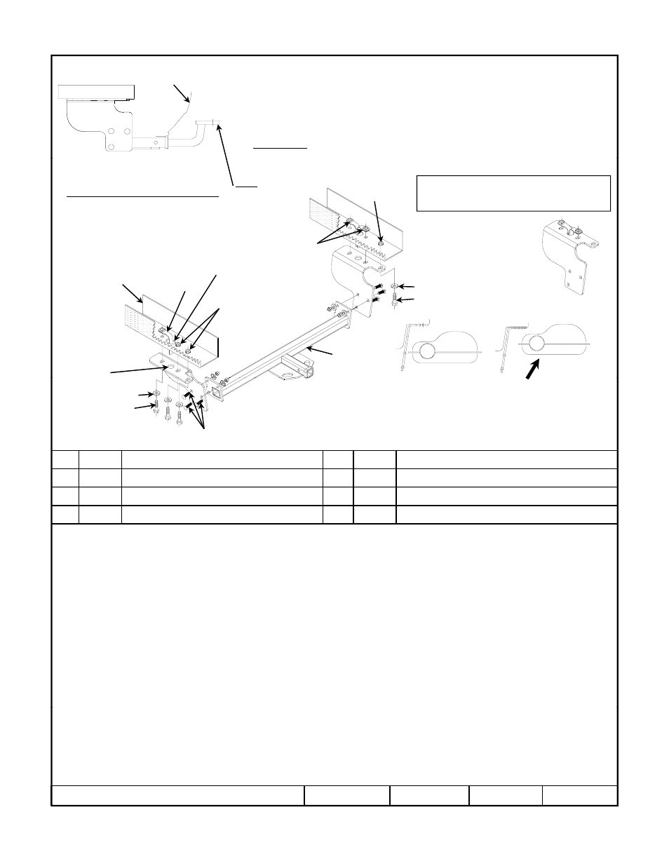
Installation Instructions
Dodge Charger
Dodge Challenger
It is recommended to have (2) people when
installing this hitch.
Part Numbers:
Do Not Exceed Lower of Towing Vehicle
Drawbar Kit:
36061
36507
90130
06128
Fascia
Hitch Shown In Proper Position
Wiring Access Location: xxx
Equipment Required:
Wrenches: 10mm, 13mm, 19mm, 3/4”,
6” Ratchet Extension, Ratchet Swivel
Do Not Exceed Lower of Towing Vehicle
Manufacturer’s Rating or
Drawbar must be used in the
RISE position only.
Fastener Kit: 36507F
3500 LB (1589 Kg) Max Gross Trailer Weight
300 LB (136 Kg) Max Tongue Weight
32
1
Existing
weldnut
Set-up handle nut assembly
prior to installation.
Access
slot
Existing
weldnuts
2
4
3
5
6
7
67
Access
hole
Frame rail
p
Both side as shown.
Center-section
of hitch
1
Qty. (3)
Hex Bolt ½-13 x 1-1/2 GR5
5
Qty. (6)
Carriage bolt 7/16-14 X 1.50 GR5
2
Qty. (6)
Conical Washer 1/2”
6
Qty. (6)
Conical Washer 7/16”
2
4
2
1
5
hole
Note: sort hardware prior to hitch installation to confirm 1/2” &
7/16” conical washer are kept with coordinated 1/2” & 7/16” bolts.
Muffler in place without
rubber isolator shown
Gently push muffler up and
outward for clearance
Recommend: two persons for installation.
1.
Lower exhaust by removing (2 (13mm socket )) exhaust hangers per side. This will allow access to frame rail by pushing the
muffler up and outward for clearance.
2.
Bend handle nut assembly prior to installation (2) on passenger side and (1) on driver side. Remove until bracket is in place.
3.
Raise passenger side bracket into place and install M12 bolt in rearward location. Gently push muffler up and outward for
clearance. Once M12 bolt is started install handle nuts through access holes and attach conical washer and hex bolt. Loosely
i t ll ll f t
3
Qty. (3)
Handle Nut Assembly 1/2-13
7
Qty. (6)
Hex nut 7/16-14
4
Qty. (3)
Hex Bolt M12 x 1.75 x 40mm CL8.8
install all fasteners.
4.
Raise drivers side bracket into position using the same method as in Step 3. Keep all fasteners loose for center-section
installation.
5.
Raise center-section of hitch into location and install 7/16” carriage bolts from outside of hitch as shown and attach 7/16 conical
and hex nuts.
6.
Check hitch is centered on vehicle.
7.
Torque all fasteners to specifications shown below.
8.
Re-attach exhaust removed in Step 1.
Tighten all M12 CL8.8 fasteners with torque wrench to 68 Lb.-Ft. (92 N*M)
z
2011 Cequent Performance Products
Sheet 1 of 3
36507N
5-23-11
Rev. A
Note: check hitch frequently, making sure all fasteners and ball are properly tightened. If hitch is removed, plug all holes in trunk pan or other body panels to
prevent entry of water and exhaust fumes. A hitch or ball which has been damaged should be removed and replaced. Observe safety precautions when working
beneath a vehicle and wear eye protection. Do not cut access or attachment holes with a torch.
This product complies with safety specifications and requirements for connecting devices and towing systems of the state of New York, V.E.S.C. Regulation V-5
and SAE J684.
Form F206 Rev A 5605
Tighten all M12 CL8.8 fasteners with torque wrench to 68 Lb. Ft. (92 N M)
Tighten all 1/2-13 GR5 fasteners with torque wrench to 50 Lb.-Ft. (68 N*M)
Tighten all 7/16-14 GR5 fasteners with torque wrench to 50 Lb.-Ft. (68 N*M)