Mako color cameras, Mako with ccd sensors, Mako with cmos sensors – ALLIED Vision Technologies Mako G-419 NIR User Manual
Page 46: Mako with ccd sensors mako with cmos sensors, 46 description of the data path
Mako Technical Manual V2.0.4
46
Description of the data path
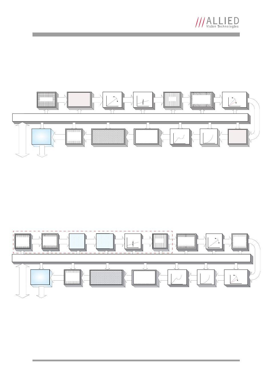
Mako color cameras
Mako with CCD sensors
Mako G-032C, Mako G-125C
Mako with CMOS sensors
Mako G-223C, Mako G-419C
Figure 35: Block diagram of Mako color cameras with CCD sensors
Figure 36: Block diagram of Mako color cameras with CMOS sensors
12 bit
HIRO
S
E I
/O
Gi
g
E
12 bit
Gamma
LUT
12
ĺ
12
1
2
bit
8 bit
8 bit
8/12 bit
Gigabit
Ethernet
interface
Frame
memory
Hue
†
Saturation
Color tranformation
Bayer
†
Interpolation
3 X 3
For on-camera interpolated PixelFormats only—outputs 8 bit.
Raw un-interpolated PixelFormats skip this block—outputs 12 bit.
†
12 bit
Horizontal
binning
§
Sensor
Analog
Analog
ADC
Offset
Analog
Analog
Gain
Vertical
binning
§
/
Vertical ROI
12 bit
Horizontal
ROI
12 bit
White balance
Camera control
§
Color information lost while binning is active.
HIRO
S
E I
/O
Sensor
array
Analog
Analog
12 bit
Gi
g
E
Analog
12 bit
Gamma
12 bit
12
b
it
Gigabit
Ethernet
interface
Internal sensor components
12 bit
12 bit
Offset
LUT
12
ĺ
12
8 bit
8 bit
8/12 bit
Frame
memory
Hue
†
Saturation
Color tranformation
Bayer
†
Interpolation
3 X 3
For on-camera interpolated PixelFormats only—outputs 8 bit.
Raw un-interpolated PixelFormats skip this block—outputs 12 bit.
‡Factory calibrated. NOT a user control.
†
Sensor
System
Gain
‡
Sensor
System
Offset
‡
Analog
Vertical
ROI
Defect
mask
12 bit
Camera control
White balance
Horizontal
ROI
12 bit
Gain
Analog
ADC