Mako output description, Mako block diagram – ALLIED Vision Technologies Mako G-419 NIR User Manual
Page 39
Mako Technical Manual V2.0.4
39
Camera interfaces
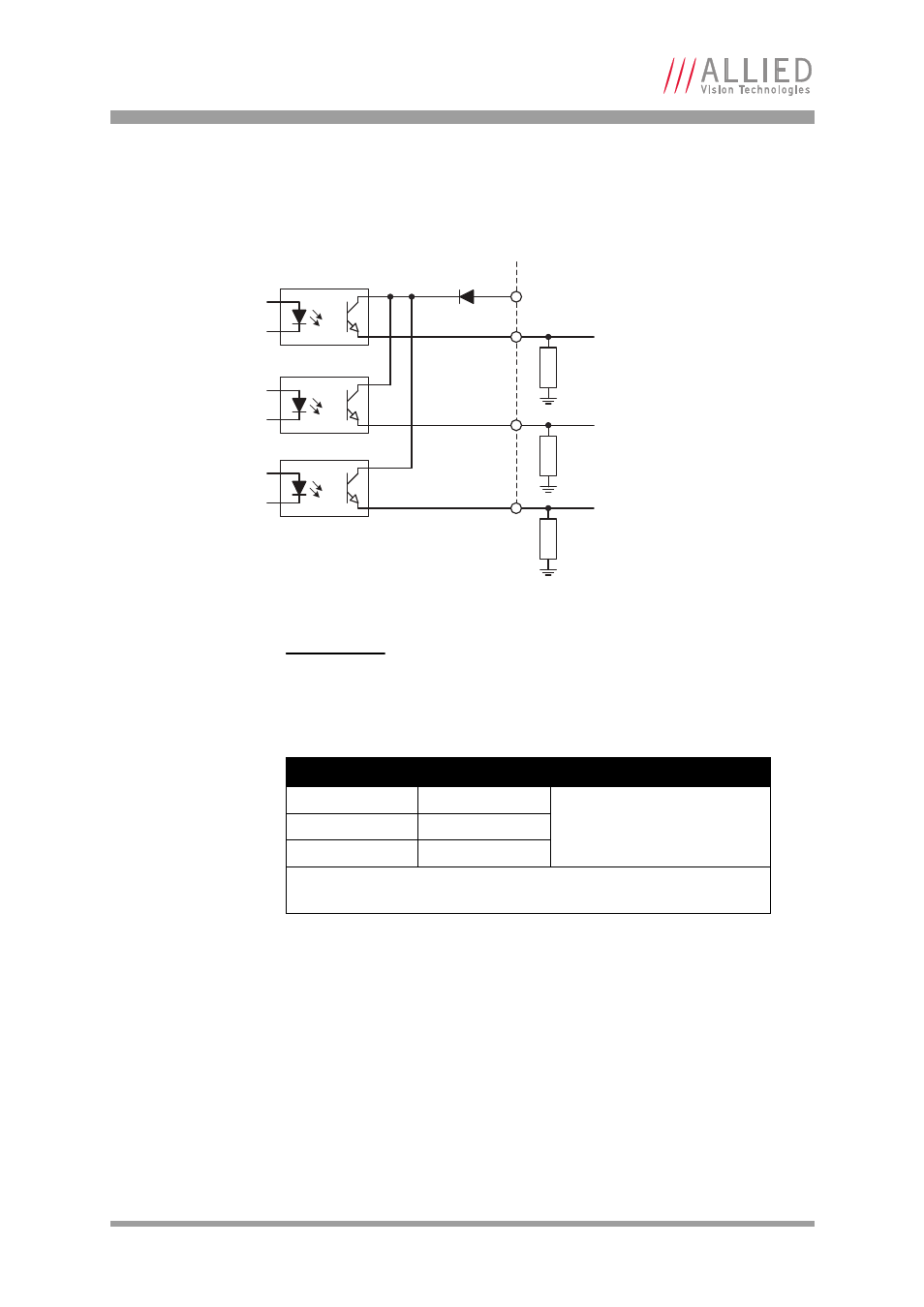
Mako output description
Mako block diagram
Figure 27: Mako output block diagram
Caution
•
Maximum 20 mA per output
•
OutVCC
30 V may damage the camera.
OutVCC
Resistor value*
5 V
1.0 k
at
5 mA minimum required
current draw
12 V
2.4 k
24 V
4.7 k
* Resistor required if GPOut1/2 connected to a device with < 5 mA draw,
i.e. high impedance
Figure 28: Mako: OutVCC and external resistor
External
Internal
OutVCC
GPOut1
GPOut2
R
R
R
GPOut3
This manual is related to the following products: