Control signals, Inputs, Input/output pin control – ALLIED Vision Technologies Mako G-419 NIR User Manual
Page 41: Outputs, Inputs input/output pin control outputs, Inputs input/output pin control
Mako Technical Manual V2.0.4
41
Camera interfaces
Control signals
The inputs and outputs of the camera can be configured by software. The differ-
ent modes are described below.
Inputs
Input/output pin control
All input and output signals that pass the I/O connector are controlled by the
I/O strobe commands.
Outputs
Output features are configured by software. Any signal can be placed on any
output. The main features of the output signals are described below:
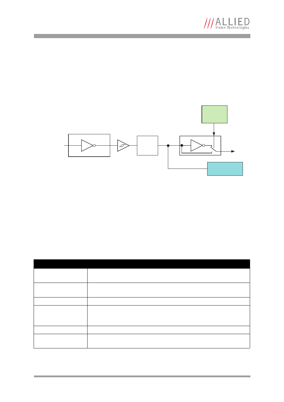
Figure 30: Input block diagram
Signal
Description
GPO
Configured to be a general purpose output, control is assigned to
SyncOutGpoLevels.
AcquisitionTriggerReady Active once the camera has been recognized by the host PC and is ready to start
acquisition.
FrameTriggerReady
Active when the camera is in a state that will accept the next frame trigger.
FrameTrigger
Active when an image has been initiated to start. This is a logic trigger
internal to the camera, which is initiated by an external trigger or software
trigger event.
Exposing
Exposing – active for the duration of sensor exposure.
FrameReadout
Active during frame readout, i.e., the transferring of image data from the CCD
to the camera memory.
Table 15: Output signals
Polarity
selectable
via software
Input state
Input signal
Optocoupler
LP filter