Mako input description, Mako input block diagram, Mako delay and minimum pulse width – ALLIED Vision Technologies Mako G-419 NIR User Manual
Page 38
Mako Technical Manual V2.0.4
38
Camera interfaces
Mako input description
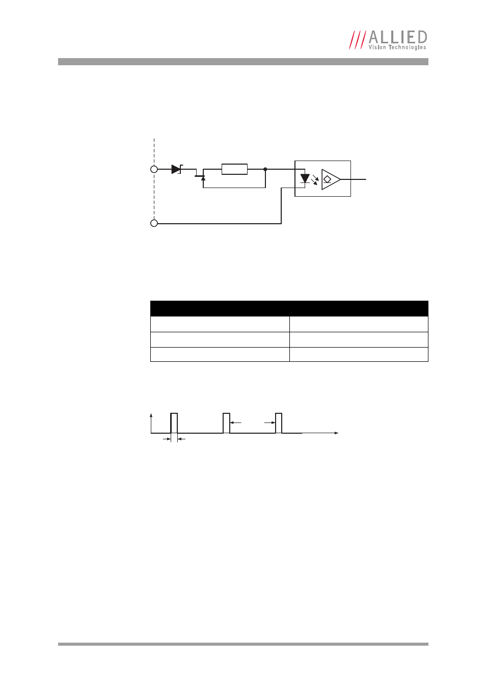
Mako input block diagram
The inputs can be connected directly to the system for voltages up to 24 V DC.
An external resistor is not necessary.
Mako delay and minimum pulse width
The minimum pulse width for all Mako cameras is:
Test conditions
The input signal was driven with 3.3 V and no external additional series resistor.
Figure 25: Mako input block diagram
Parameter
Value
U
in
(low)
0–1.0 V
U
in
(high)
3–24 V
Current (constant-current source)
3–4 mA
Table 13: Mako input parameters
Figure 26: Mako minimum pulse width
GPIn1
InGND
External Internal
180R
I
F
0
t
44 μs
6 μs
20 kHz
This manual is related to the following products: