3 - controls and components, 4 - use of the wheel balancer – CEMB USA C88 (B) User Manual
Page 9
I 0709 - 9
3
GB
3 - CONTROLS AND COMPONENTS
3.1
►
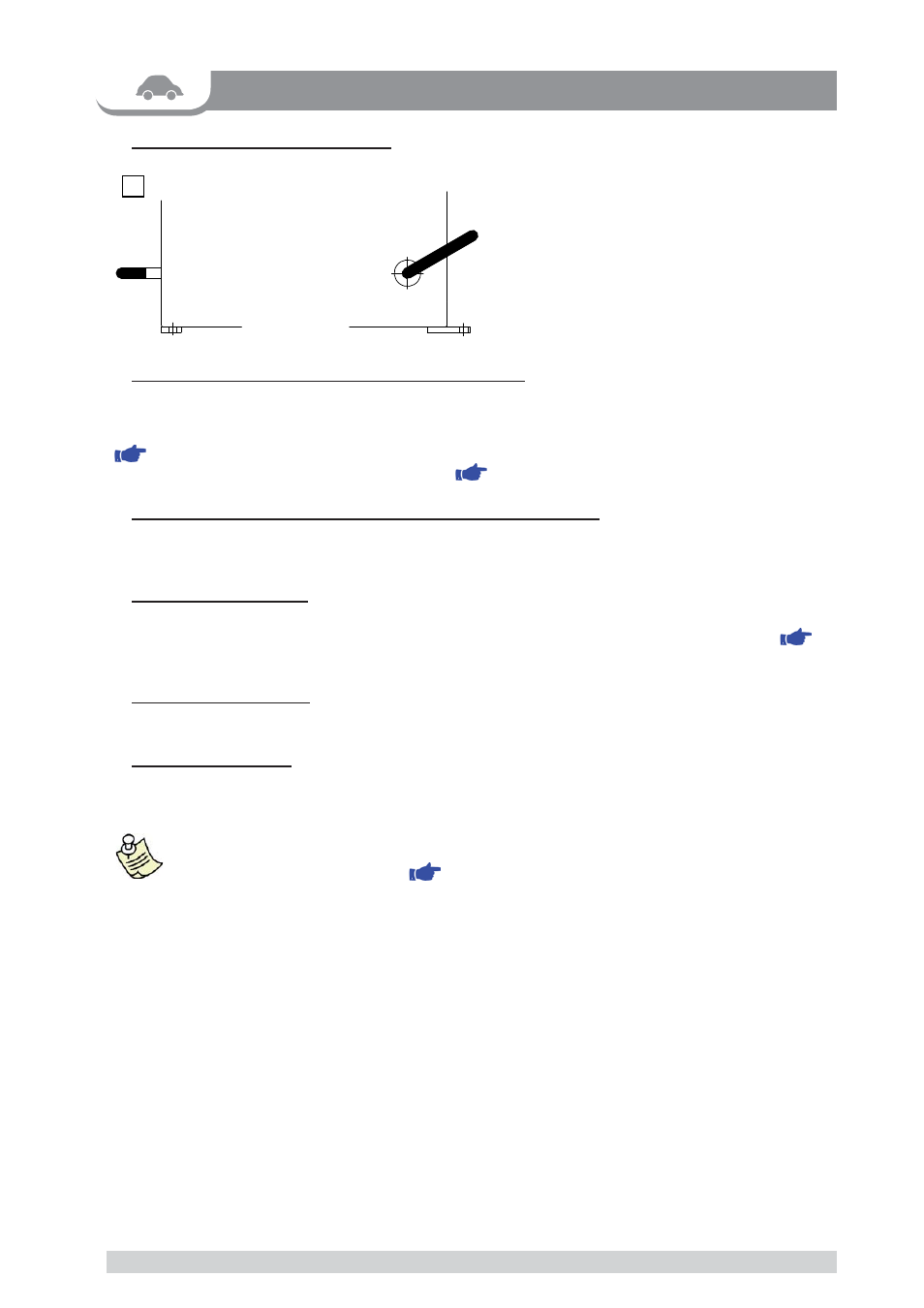
- PNEUMATIC LOCKING PEDAL
This pedal allows releasing the device faste-
ning the wheel on the adapter. Do not actuate
this pedal during the machine cycle and/or
when adapters other than the standard cone
adapter are mounted.
The pedal has two stable positions: top,
wheel unclamped; bottom, wheel clamped.
3.2 - AUTOMATIC DISTANCE AND DIAMETER GAUGE
►
This gauge allows measurement of the distance of the wheel from the machine and the wheel diameter at the point of
application of the counterweight.
It also allows correct positioning of the counterweights on the inside rim by using the specifi c function
(
INDICATION OF EXACT CORRECTION WEIGHT POSITION
) which allows reading, on the monitor, the position
used for the measurement within the rim (for calibration
CALIBRATION
).
3.3
►
- SONAR DEVICE FOR AUTOMATIC WIDTH MEASUREMENT
Measures the distance of the wheel without mechanical contact simply by closing the guard every time a valid mea-
surement has been made with the
AUTOMATIC DISTANCE AND DIAMETER MEASUREMENT GAUGE
.
3.4 -
►
CLOCK CONTROL
The wheel balancing machine is provided with a clock having a back-up of about one month with the machine
switched off. If the machine remains unused for a long period, check date and time settings when restarting (
CLOCK SET-UP
).
3.5 - P
►
RINTER (OPTION)
Used to print useful information for the vehicle, residual imbalance and eccentricity for the balanced tyre.
3.6 - TOUCH SCREEN
►
The function keys are selected by pressing on the touch screen.
Tou
▪
ch the screen with the fi ngers only: never use the counterweight pincers or other pointed objects.
When the beep signal is enabled (
▪
ACOUSTIC SIGNAL
), pressing of any push button is accompa-
nied by a “beep”.
4 - USE OF THE WHEEL BALANCER