Agilent Technologies 75000 SERIES B User Manual
Page 31
Example: Digital
Output Configuration
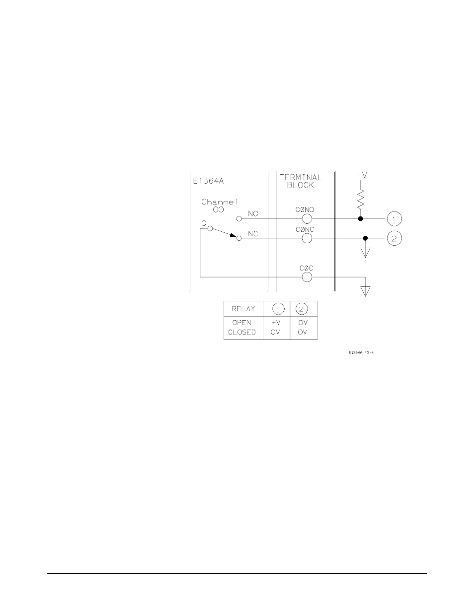
Figure 3-4 shows channel 00 configured for digital output operation. When
the channel 00 relay is open (NC connected to C), point 1 is at + V and point
2 is at 0 V. When the channel 00 relay is closed (NO connected to C), points
1 and 2 are both at 0 V. (This configuration is useful for 24V or 48V control
logic, since this type of application cannot be met with the configuration
shown in Chapter 2, Figure 2-5.) To close channel 00, execute:
CLOS (@100)
Close channel 00 relay (connect
NO to C). 1 is the card number and
00 is the channel number.
To open channel 00, use
OPEN (@100)
.
Figure 3-4. Example: Digital Output Configuration
Chapter 3
Using the Agilent E1364A Form C Switch 29