8 operation explanation, Installation and connection – DE-STA-CO F5-B AC Inverter Drive User Manual
Page 29
29
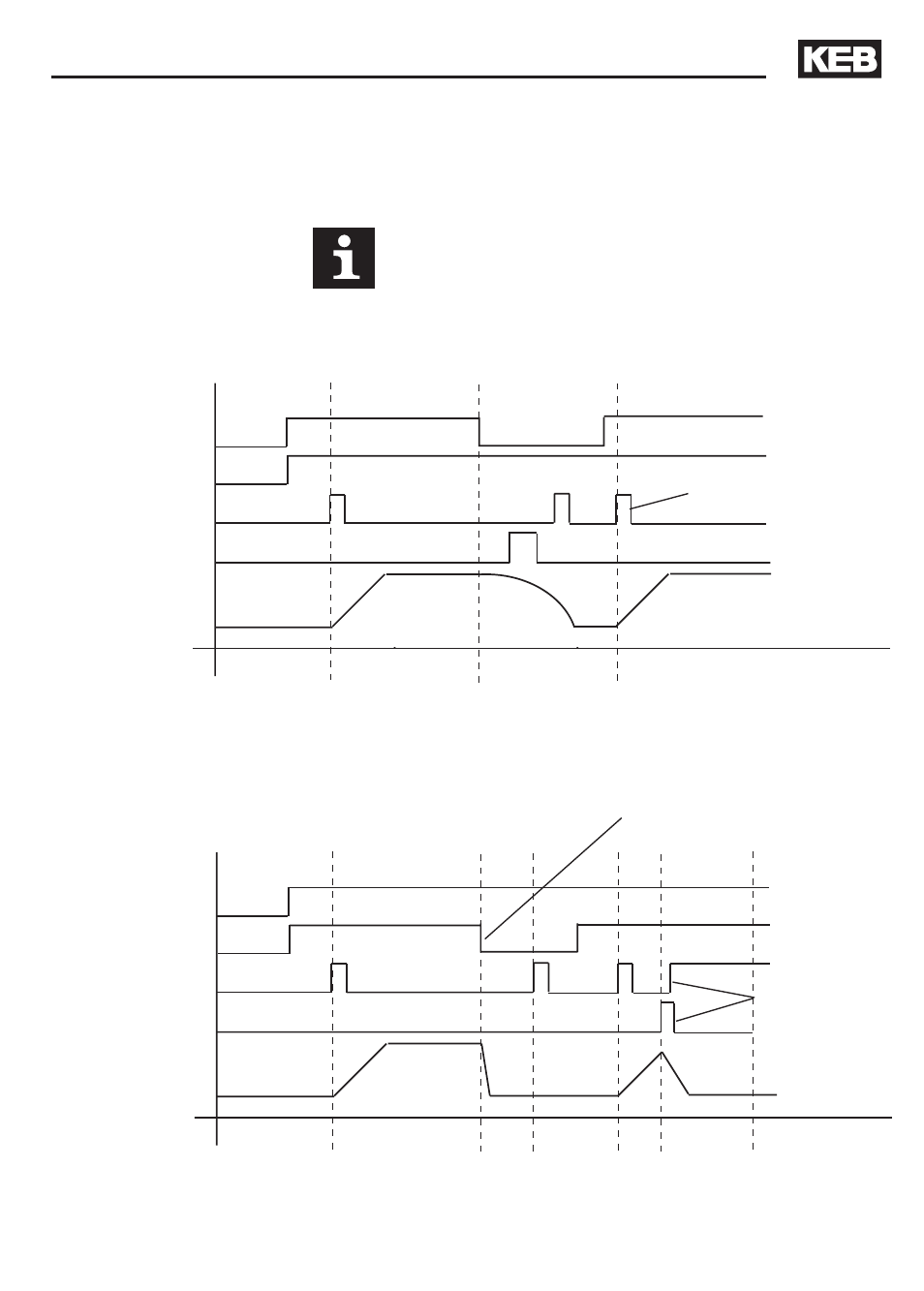
As a momentary signal is sent to INPUT 14 the drive indexes until it
receives a signal on INPUT 11. On reception of signal on INPUT 11 the
drive either decelerates and stops or the stop point is delayed for a
positioning stop. This depends on the value entered in CP.27.
3.5.8 Operation
Explanation
Installation and Connection
ST
(pin 16)
Quick Stop
(pin 10)
Start
(pin 14)
Stop
(pin 11)
Motor
(RPM)
Drive reactivates into indexing mode - motor stopped condition
or Quick Stop mode depending on Quick Stop input!
ST: Loss of signal shuts off the motor voltage - the motor will coast to a stop
Quick Stop: Ignored
Start pulse: Ignored
Stop signal: Ignored
ST
(pin 16)
Quick Stop
(pin 10)
Start
(pin 14)
Stop
(pin 11)
Motor
(RPM)
ST: Must be high
Quick Stop: Loss of signal decelerates the load to a stop
Start pulse: Ignored
Stop signal: Ignored
Drive reactivates into indexing mode - motor stopped condition!
In the index mode, the start pulse
takes priority over the stop pulse.
Disabled Mode - Motor Voltage Off
6ms minimum pulse
6ms minimum delay between
Quick Stop and Start
6ms minimum
pulse
Quick Stop Mode - Stop Motor