Installation, Package contents, Room alert 4e id box – AVTECH Room Alert 4ER Monitor (RA4E-ES1-RAS) User Manual
Page 7
AVTECH Software Inc.
3
Room Alert 4E
Installation
Installation
The initial installation of the Room Alert 4E can be completed quickly and easily provided the
instructions below are followed with detail and care. Before beginning, please lay out the contents of the
Room Alert 4E package so that the components can all be located and accessed with ease.
Package Contents
The main components included with the standard (default) Room Alert 4E package include:
• One (1) Room Alert 4E ID Box (1U 19˝ Mounting Bracket Is Included w/Room Alert 4ER)
• One (1) Ethernet Cable (10’ length, red)
• One (1) AVTECH 5V 1A Power Adapter (110-240V, 50-0Hz, RoHS)
• One (1) External Digital Temperature Sensor
• One ()
Room Alert 4E User’s Guide & Reference Manual (you’re reading it)
• One (1) AVTECH Install & Update CD
• One (1) Package Of Literature & Additional Information
NOTE: Some of the components arriving with this package may be individually wrapped and contain additional supporting
components. Please remember to keep these components together as they will be required for proper setup. If you received
additional components (i.e. like additional sensors) that are not mentioned above, instructional material explaining the proper
setup of that component should be included with it. If you cannot fi nd the proper instructional materials, check the included CD
or ‘Support’ and ‘Downloads’ sections of the AVTECH.com website for any appropriate installation or application note that will
instruct you on the proper installation and use of that component. Install those components after the Room Alert 4E setup is
completed.
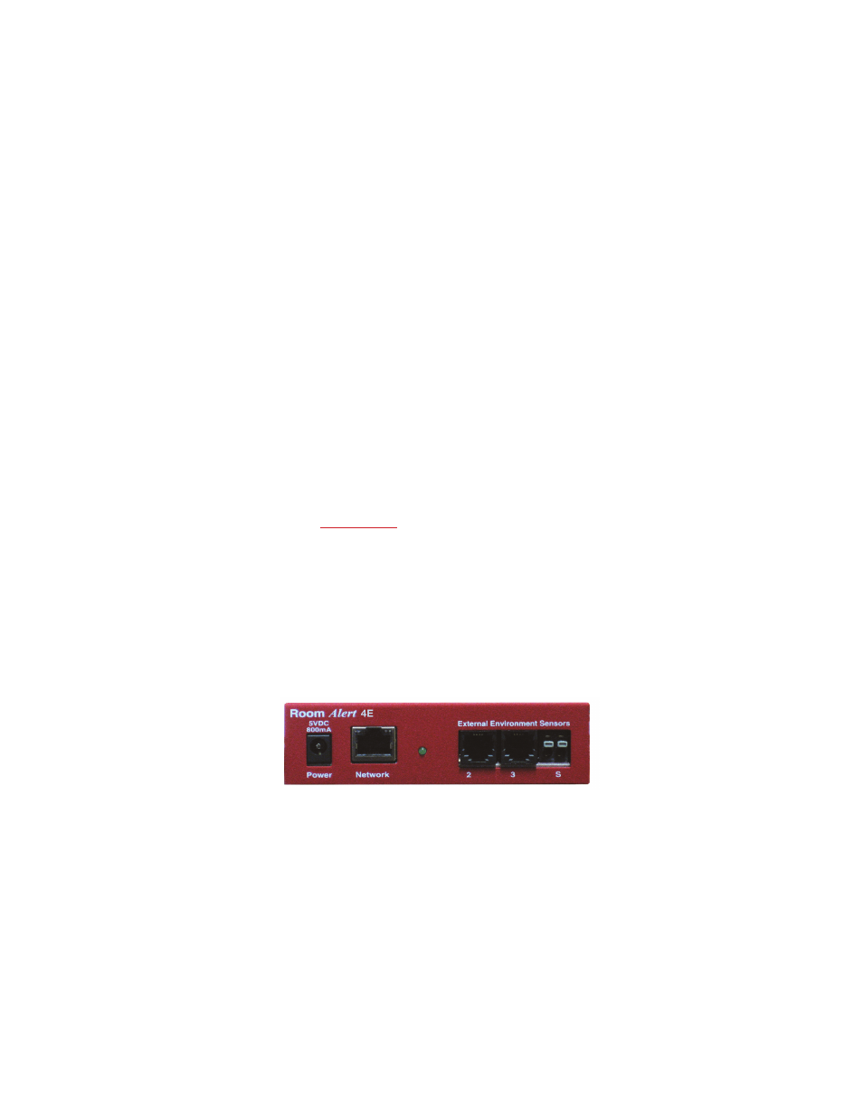
Room Alert 4E ID Box
The graphics below identify the primary components of the Room Alert 4E ID box that are visible on the
front and rear panels.
A
B
C D
Front View (Room Alert 4E ID Box)
Main Power Port — Connect the ‘AVTECH 5V 1A Power Adapter’ to this port to power the
Room Alert 4E unit. Do not use any other power adapter or it could damage the unit.
Network Port — Attach the Room Alert 4E unit to the network by plugging the Ethernet
cable into this port and then connecting the other end to the network. The left LED above the
‘Network’ port indicates Link status and should light up and remain a solid green or orange color.
The right LED above the ‘Network’ port indicates Activity status and should blink with network
activity on the port. The color of this LED can be green or orange as well. When the device
reboots, the Link LED will turn on and off several times. If the Link LED remains unlit and the
A.
B.