Atec PMM-9010_9030_9060 User Manual
Page 14
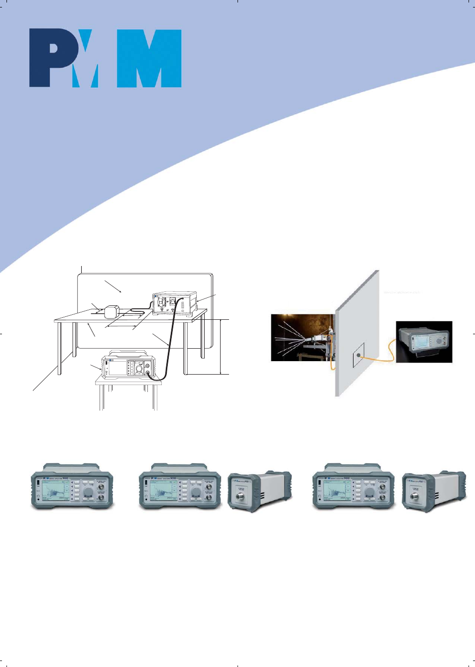
Conducted tests
up to 30 MHz
Interference
measurements with
optional rod antenna
Radiated measurements with PMM 9030/9060 mounted directly on
an antenna connector
Example of Test Setup for RFI Voltage Measurement
All kinds of conducted and radiated
measurements up to 3 GHz (CISPR 11 group
1; CISPR 11 group 2 with operating frequency
< 400 MHz; CISPR 12;
CISPR 13; CISPR 14-1; CISPR 22 when the
highest internal source frequency is up to 500
MHz; future CISPR 32 when the highest
internal source frequency is up to 500 MHz)
Conducted and radiated measurements up to
6 GHz (as above plus: CISPR 22, any frequency
of internal source; future CISPR 32, any
frequency of internal source but except
outdoor units of direct to home
satellite receivers)
PMM 9010
PMM 9010 + PMM 9030
PMM 9010 + PMM 9060
Configurations and application examples
Vertical ground plane, min. size 2x2 m
Power cord
40 cm
40 cm
> 80 cm
LISN
bonded to
ground
plane
Non conductive plane
Coax clable
Test
receiver
80 cm
SIGNAL ANALYZER
9010
USB
PW
Esc
RF OUTPUT 50
W
10Hz - 50 MHz
RF INTPUT 50
W
10Hz - 30 MHz
0dB
ON
Test-Chamber
PRF-Chamber