Vector modulation – Atec Agilent-E8267D User Manual
Page 17
17
1. With Option 007, vector modulation is not useable in ramp sweep mode. With Option 1EH, specifications apply with filters off.
2. For optimum signal quality, the I and Q inputs should be 0.7 V
peak
, with
√
(I
2
+ Q
2
) + 150 mV
rms
. Different RMS levels are
accommodated by adjusting the internal I/Q modulator attenuator, which may be either manually or automatically set. The
minimum
input level required to maintain RF level accuracy is
√
(I
2
+ Q
2
) = 0.1 V
rms
.
3. Sine wave response, measured with input level = 100 mVrms on one channel, and ALC off. For carrier frequencies below
1.5 GHz, modulation frequency response within ± 150 MHz of carrier may be limited by RF chain filtering.
External I/Q inputs
Input impedance switched
50 or 600 Ω (nom)
Input range
2
Minimum 0.1 V
rms
, maximum 1V
peak
Flatness
± 1 dB within ± 40 MHz of carrier (with ALC off) (typ)
I/Q frequency response
3
(measured)
RF path filters
Carrier frequency
Nominal filter cutoff
≤ 250 MHz
300 MHz low-pass filter
> 250 to 396 MHz
220 to 420 MHz bandpass filter
> 396 to 628 MHz
350 to 650 MHz bandpass filter
> 628 to 1000 MHz
1040 MHz low-pass filter
> 1.0 to 1.5 GHz
1.6 GHz low-pass filter
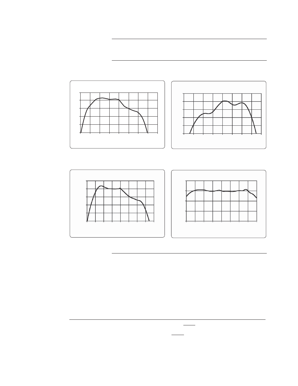
Vector modulation
1
1.8 GHz
900 MHz
Carrier at 900 MHz (measured)
2
0
-2
-4
-6
-8
(dB)
Offset from Carrier (GHz)
-0.2 -0.15 -0.1 -0.05 0 0.05 0.1 0.15 0.2
Carrier at 1.8 GHz (measured)
(dB)
Offset from Carrier (GHz)
-0.2 -0.15 -0.1 -0.05 0 0.05 0.1 0.15 0.2
2
0
-2
-4
-6
-8
38 GHz
2.4 GHz
Offset from Carrier (GHz)
-0.2 -0.15 -0.1 -0.05 0 0.05 0.1 0.15 0.2
(dB)
Carrier at 2.4 GHz (measured)
2
0
-2
-4
-6
-8
Carrier at 38 GHz (measured)
Offset from Carrier (GHz)
(dB)
5
0
-5
-10
-15
-0.2 -0.15 -0.1 -0.05 0 0.05 0.1 0.15 0.2