Atec Anritsu-ME7838A User Manual
Page 24
24
PN: 11410-00593 Rev. D
ME7838A BB/mm-Wave VNA TDS
Waveguide Bands from 50 GHz to 750 GHz
VectorStar ME7838A BB/mm-Wave VNA
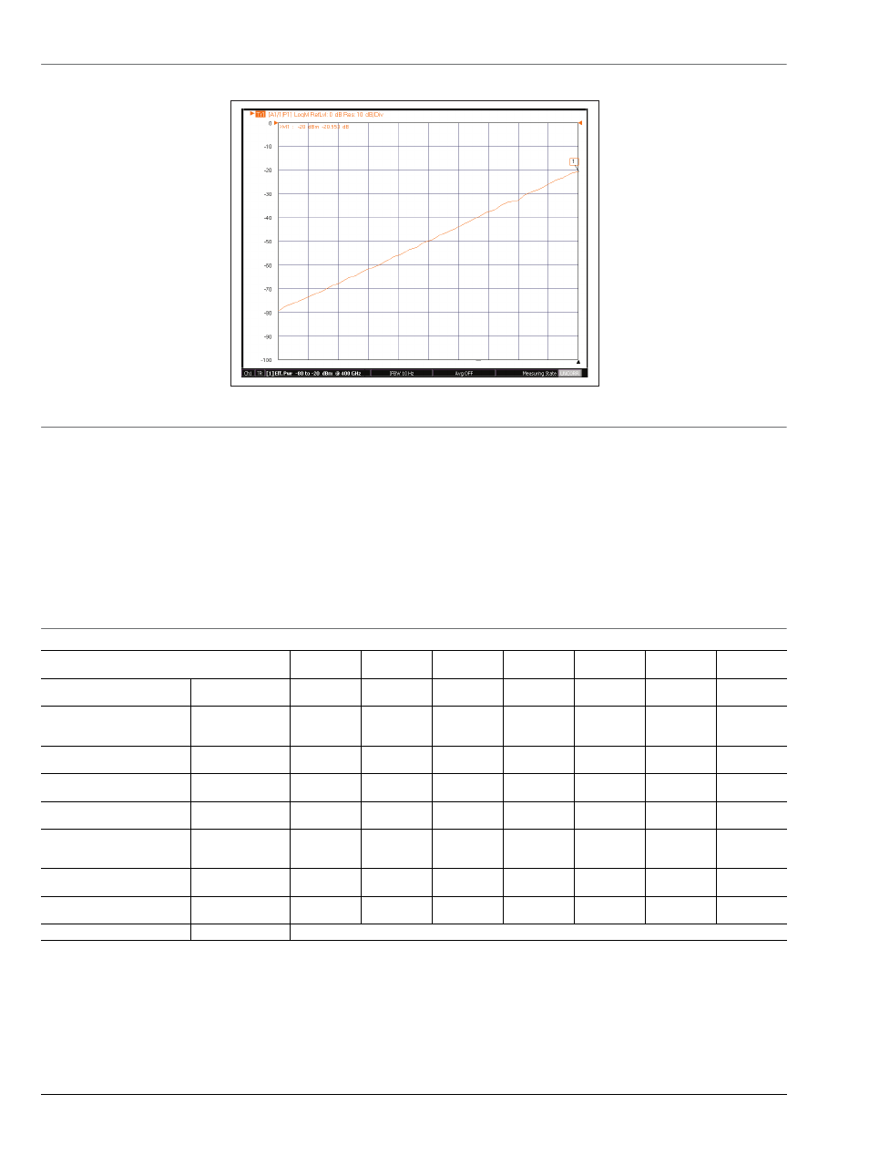
ME7838A 400 GHz Power Sweep with VDI WR2.2 TxRx Module
Real time power sweep of VDI WR2.2 module using system power level control and no mechanical attenuators.
4.8 VectorStar ME7838A Millimeter-Wave System with OML Modules
This section provides specifications for the
VectorStar MS4640A series microwave Vector Network Analyzers (VNAs) when configured with the OML millimeter-wave frequency extension
modules.
Description
Each OML module must be equipped with a dedicated external power supply and DC cable. Connection
between the VectorStar and the OML mm-Wave module is provided with the supplied interface cable.
System Configuration
The VectorStar Millimeter-Wave system provides control of OML modules for frequency extension coverage
up to 325 GHz. The MS4640A series VectorStar VNA may be configured for mm-Wave operation by adding
the appropriate control option and test set.
System requirements
MS4642A, MS4644A, MS4645A, or MS4647A Model VectorStar VNA
MS4640A Option 007, Receiver Offset
MS4640A Option 080, 081, 082, or 083
SM6537 Interface Cable
3739B Test Set
Specifications
Dynamic range specifications are valid for any MS4640A VectorStar VNA with appropriate options.
Directivity specifications are valid when using appropriate OML calibration kits.
4.9 OML Millimeter-Wave Extenders Summary Specifications
Specifications are typical and subject to change without notice.
V15VNA2-
T/R
V12VNA2-
T/R
V10VNA2-
T/R
V08VNA2-
T/R
V06VNA2-
T/R
V05VNA2-
T/R
V03VNA2-
T/R
WR-15
50 – 75
WR-12
60 – 90
WR-10
75 – 110
WR-08
90 – 140
WR-06
110 – 170
WR-05
140 – 220
WR-03
220 – 325
+5
+8
+2
+5
+3
+5
-8
-4
-15
-10
-18
-13
-23
-
+8
+8
+6
+4
-5
-5
-5
> 17
> 17
> 17
> 17
> 15
> 15
> 9
> 35
> 35
> 35
> 35
> 35
> 35
> 33
92
> 105
92
> 105
95
> 110
90
> 105
80
> 95
80
> 95
60
> 75
± 0.2
± 2
± 0.2
± 2
± 0.2
± 2
± 0.3
± 3
± 0.4
± 5
± 0.4
± 6
± 0.4
± 8
> 35
> 35
> 35
> 33
> 30
> 30
> 30
13.0" x 4.3" x 2.7"
OML "T/R" Models
System Operating
Frequency
a
a. Test Port Flange Configuration is compatible with MIL-DTL-3922/67D (UG 387/U-M)
(GHz)
Test Port Output Power
b
b. As there are no internationally recognized power standards above 110 GHz, any power data supplied above 110 GHz is traceable only to OML's
calorimeter.
Minimum
Typical
(dBm)
Test Port Input Power
@ 0.1 dB Compression
c
c. Not Tested
Typical
(dBm)
Test Port Match
c
Typical
(dB)
Residual Source & Load
Match
Typical
(dB)
Test Dynamic Range
d
d. Measured at 10 Hz IF bandwidth.
Minimum
Typical
(dB)
Reflection &
Transmission Tracking
e
e. At +25 °C. Measured for 1 hr after 1 hr warm-up. Based on “perfect” RF and LO test cables not moved after warm-up and calibration. Not
tested.
Magnitude (dB)
Phase (deg.)
Coupler Directivity
c
Typical
(dB)
Size
f
f. Height excludes the adjustable rubber feet; length and depth dimensions exclude the output waveguide length.
(L x W x H)