3 system configuration with vdi modules, 4 vdi module specifications, 5 vdi module head configurations – Atec Anritsu-ME7838A User Manual
Page 22
22
PN: 11410-00593 Rev. D
ME7838A BB/mm-Wave VNA TDS
Waveguide Bands from 50 GHz to 750 GHz
VectorStar ME7838A BB/mm-Wave VNA
4.2 VectorStar ME7838A Millimeter-Wave System with VDI Modules
This section provides the specifications for the VectorStar MS4640A series microwave Vector Network Analyzers (VNAs) when configured with the
Virginia Diodes, Inc. millimeter-wave (mm-Wave) frequency extension modules. The following frequency bands are supported:
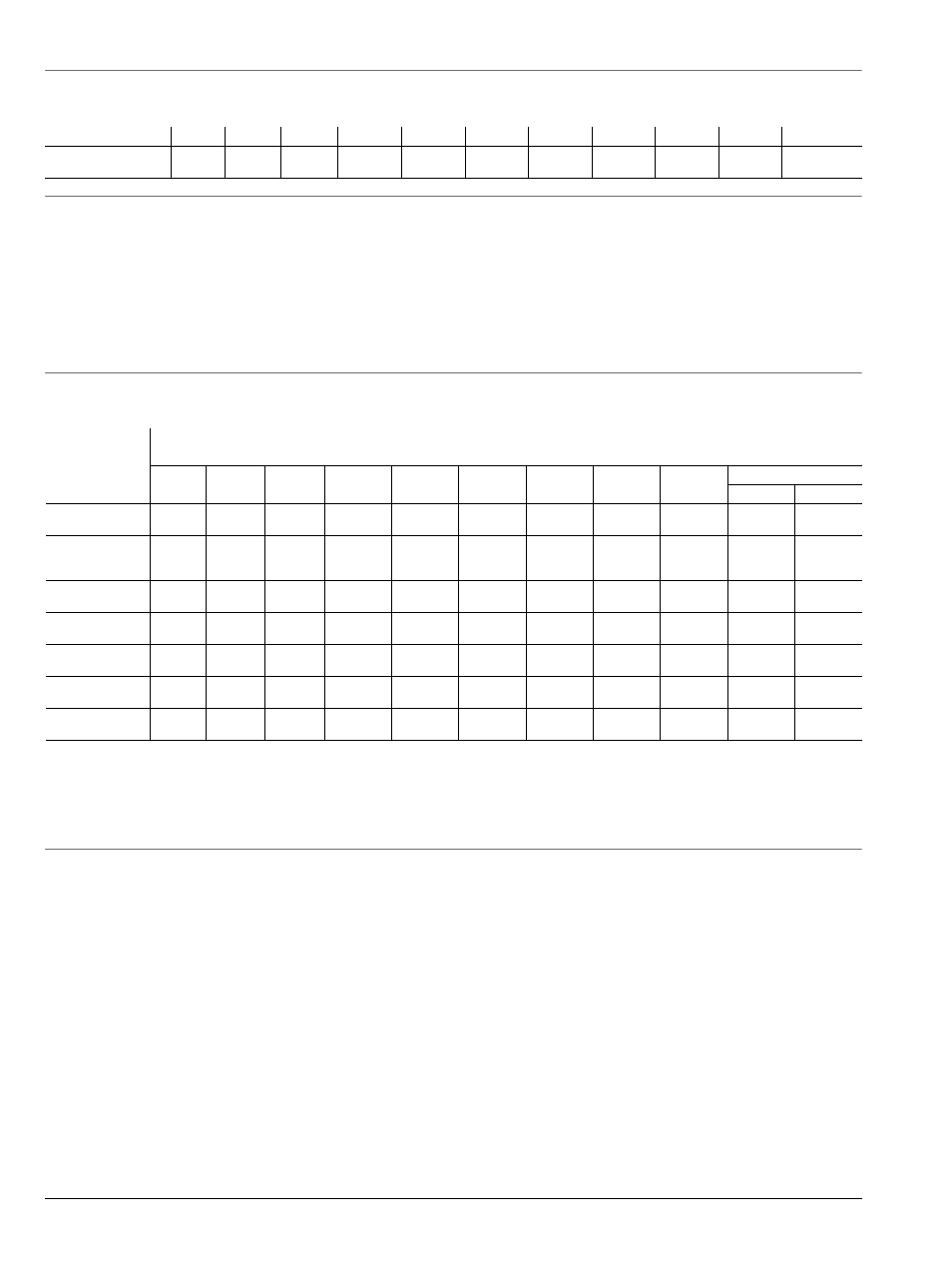
Waveguide Band
WR15
WR10
WR8.0
WR6.5
WR5.1
WR4.3
WR3.4
WR2.8
WR2.2
WR1.5
WR1.0
a
a. Contact Anritsu
Frequency (GHz)
50 to
75
75 to
110
90 to
140
110 to
170
140 to
220
170 to
260
220 to
400
260 to
400
325 to
500
500 to
750
750 to
1100
4.3 System Configuration with VDI Modules
The VectorStar Millimeter-Wave system provides control of VDI modules for frequency extension coverage up to 750 GHz and beyond. MS4640A
series VectorStar VNA may be configured for mm-Wave operation by adding the appropriate control option and test set. System requirements
include:
• MS4642A, MS4644A, MS4645A, or MS4647A Model VectorStar VNA
• MS4640A Option 007, Receiver Offset
• MS4640A Option 080, 081, 082, or 083
• SM6537 Interface Cable
• 3739B Test Set
Each VDI module is equipped with a dedicated external power supply and DC cable. Connection between VectorStar and the VDI mm-Wave
module is provided with the supplied interface cable.
4.4 VDI Module Specifications
Dynamic range and stability specifications are valid for any MS4640A VectorStar VNA with appropriate options. Directivity specifications are valid
when using appropriate VDI calibration kits.
Waveguide
Band (GHz)
VDI Millimeter-Wave Extenders Summary Specifications
a
a. Specifications. These results assume a through measurement with two TxRx Heads. The specifications quoted here are "expected" and subject
to change. Stability is for 1 hour after a 1 hour warm-up, in a stable environment with ideal cables. The dynamic range (RBW 10 Hz) is
measured by first connecting two TxRx heads together and normalizing the un-calibrated S
21
. The heads are then disconnected and
terminated with a waveguide load. The RMS of the measured S
21
parameter is the system dynamic range.
Band / Frequency Range (GHz)
Dynamic
Range
b
b. Typical. BW = 10 Hz, dB, typical.
120
120
120
120
120
110
100
100
100
100
90
Minimum
Dynamic
Range
c
c. Typical. BW = 10 Hz, dB, minimum.
100
100
90
90
90
85
80
80
80
80
75
Magnitude
Stability (± dB)
0.15
0.15
0.15
0.25
0.25
0.3
0.3
0.5
0.5
0.8
0.8
Phase Stability
(± deg.)
2
2
2
4
4
6
6
8
8
10
11
Test Port Power
(dBm)
3
3
0
0
-3
-6
-9
-16
-17
-25
-25
Directivity
(dB)
30
30
30
30
30
30
30
30
30
30
30
Maximum
Dimensions
d
d. Dimensions: L x W x H dimensions in inches.
11x5x3
11x5x3
11x5x3
11x5x3
11x5x3
11x5x3
11x5x3
11x5x3
11x5x3
11x5x3
11x5x3
4.5 VDI Module Head Configurations
TxRx
Transmitter with two Receivers (Reference and Measurement), and two couplers. Two TxRx heads are
required for full two-port measurements.
TxRef
Transmitter with Reference Receiver and one coupler.
Rx
Measurement Receiver.
WR15
50-75
WR10
75-110
WR8.0
90-140
WR6.5
110-170
WR5.1
140-260
WR4.3
170-260
WR3.4
220-325
WR2.8
260-400
WR2.2
325-500
WR1.5
500-700
700-750