Option 012 – Atec Agilent-8720D User Manual
Page 9
9
Option 012
Option 012 adds RF loops that provide direct
access to the A and B samplers in the port 1 and
port 2 receivers. This allows transmission meas-
urements that bypass the receiver coupler for
improved signal-to-noise and sensitivity. The system
is capable of antenna measurements to –110 dBm at
40 GHz, and filter rejection measurements to 120 dB.
Use of multiple antennae provides improved signal-
to-noise for free space transmission and reflection
measurements. The RF loops can also be used to
integrate components into the test set. Adding a
20 dB attenuator increases the test port 0.1 dB
compression level to +30 dBm. With front panel
jumpers installed, the system operates as a stan-
dard system and meets standard instrument speci-
fications.
Supplemental characteristics (Option 012)
Frequency Range (GHz)
0.05 to 0.5 0.5 to 2
2 to 8
8 to 20
20 to 40
Compression
1
Test Port
1,2
20 dB
16 dB
15 dB
8 dB
3 dB
Compression
1
Direct
Sampler Input
2 dBm
1 dBm
0 dBm
-7 dBm
-12 dBm
Average
Noise Floor
2
-125 dBm
-125 dBm -125 dBm -123 dBm -120 dBm
Receiver
Dynamic Range
127 dB
126 dB
125 dB
116 dB
108 dB
1. Input power level that causes 0.1 dB compression in the receiver
2. 10 Hz IF BW
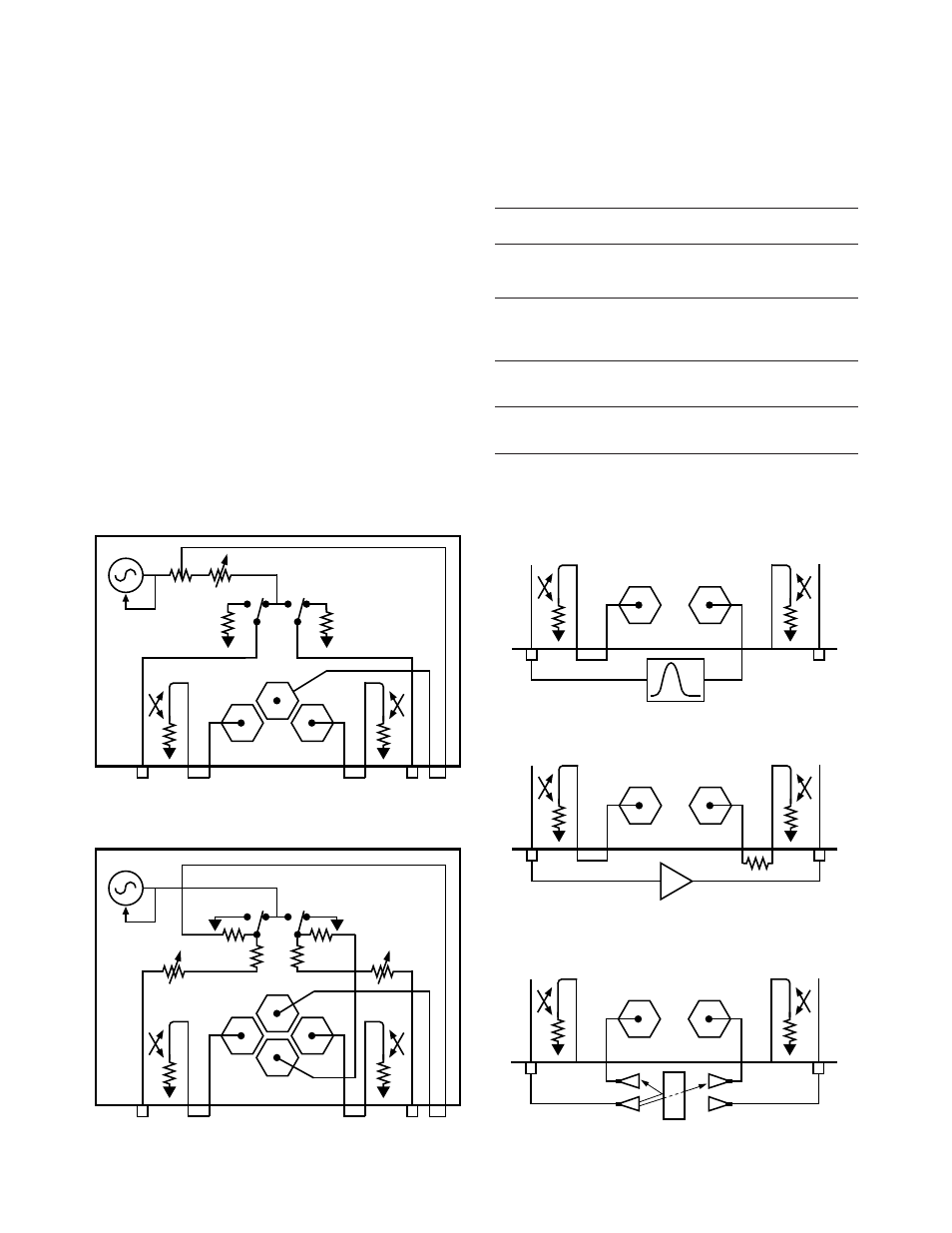
Option 012 test set block diagram
Option 400 and 012 test set block diagram
Measure filter rejection to –120 dB
Transfer
Switch
Source
Port 1
Port 2
Samplers
A
R
B
R channel
jumper
Switch
Splitter
Source
Port 1
Port 2
Samplers
A
R
R2
B
R channel
jumper
Samplers
A
B
Measure amplifier output to +43 dBm
Samplers
A
B
16 dB more sensitivity for antenna test. Improved
signal to noise for free space materials test.
Samplers
A
B