Hip & ridge detail headwall detail valley detail – ATAS Field-Lok User Manual
Page 3
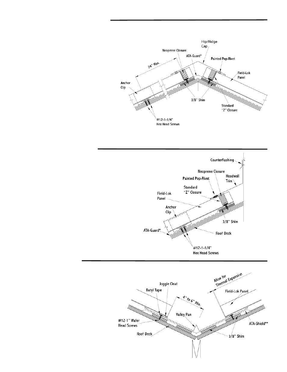
Hip & Ridge Detail
Headwall Detail
Valley Detail
Hip and ridge applications are handled
in the same manner.
1. Install underlayment to roof edge.
Place 3/8” shim as shown.
2. Cut “Z” closure to fit between seams and install in
butyl tape. Fasten through 3/8” shim to secure
panel (Use 4 fasteners on 13 3/4”, 5 on 18” )
3. Seal neoprene strips into “Z” closures .
4. Snap hip/ridge cap over “Z” closures for it to lock
into place. Pop-rivet one side only to allow for
expansion and contraction.
Notes:
* Trim must be pop-riveted to Z in at least one
location to control thermal movement.
* Unless otherwise specified, all fasteners for trim
components should be spaced at 2’-0” o.c.
* Install splice plates at ridge cap joints. Pop rivet
splice to one end of ridge cap to allow for
expansion and contraction.
.
1. Install underlayment to roof edge.
Place 3/8” shim as shown.
2. In standard headwall situation (without venting),
run underlayment from roof plane up headwall.
Install panels up to headwall.
3. Fasten “Z” closure in bed of sealant at top of
panel. Fasten through 3/8” shim to secure panel.
(Use 4 fasteners on 13 3/4”, 5 on 18” )
4.Seal neoprene closure into “Z” closure.
5. Install headwall transition over “Z” closure.
6. Apply counterflashing over the headwall trim,
as required.
1. Install ATA-Shield** approximately 18” up
both sides of the valley line.
2. Place 3/8” shim as shown.
3. Lay valley pan in valley center. Locate joggle
cleat at 4” to 6” from valley center.
4. Install joggle cleat. Fasten 6” o.c. through
butyl tape and pan into 3/8” shim and substrate.
5. Turn under edge of panel to slide into
joggle cleat. Fasten with clips at 2’-0” o.c.