Fig. 7-2, the 18-pin jumper – Alpha Technologies AlphaNet DSM Series DOCSIS User Manual
Page 46
46
745-814-B0-001, Rev. A
7.0
Hardware Installation, continued
7.2
Hardware Installation Procedure, continued
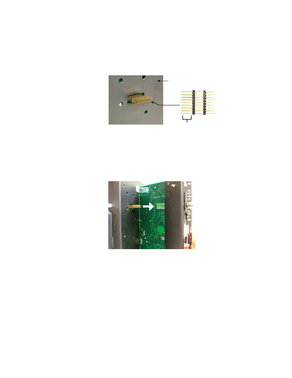
6. Locate the 18-pin jumper and insert the long side of the jumper firmly into the
side of the inverter module.
7. Unpack the XP-DSM. If not yet done, record the MAC addresses from the front
of the unit, and report it to the network manager for network provisioning (see
9. Secure the XP-DSM to the inverter module by tightening the two captive screws.
10. Reinstall the inverter module and reconnect the ribbon cable. Make front panel
connections (tamper, RTS, battery sense, etc.).
8. Line up the 18-pin jumper with the XP-DSM connector and connect the unit to the
inverter module.
Insert Long Side Into Inverter Module
Inverter Module
Fig. 7-2, The 18-pin Jumper
Fig. 7-3, Connecting the Transponder to the Inverter Module
- AlphaCell GelCell Series (32 pages)
- FXM 650, 1100, 2000 UPS (96 pages)
- Cordex 48-1.2kW (68 pages)
- Radium MiniBay (57 pages)
- Fiber Backhaul Enclosure (FBE) (19 pages)
- FBE2322 Enclosure System (38 pages)
- FlexNet PMR, GMR Series (49 pages)
- Te25xh (38 pages)
- FlexNet MPS48-12M - Technical Manual (33 pages)
- FlexNet MPS48-12M - Quick Start Guide (2 pages)
- FlexNet ELPM 300-48D (25 pages)
- FlexNet FMPS (40 pages)
- FlexPoint AX Series (34 pages)
- FlexPoint FPR1207-F - Technical Manual (18 pages)
- FlexPoint FPR1207-F - Quick Start Guide (2 pages)
- AlphaGen PN-6x-T 7.5kW 48VDC - Installation and Operation Manual (79 pages)
- AlphaGen CE-3x2 5K-T 48Vdc (95 pages)
- AlphaGen PN-6x-T 7.5kW 48Vdc (95 pages)
- AlphaGen 3.5_5.0kW Kohler COM5 (80 pages)
- Security Bar Field For UPE-3, UPE-6, UPE-M3, UPE-M6, PN Series and CE Series (2 pages)
- AMPS80 HP (116 pages)
- 255A Bypass Switch (24 pages)
- AMP24 HP (108 pages)
- FXM350_Micro350 UPS (112 pages)
- CFR 600, CFR 600XT, CFR 1000 (70 pages)
- BPS Series Bypass Switch (36 pages)
- CFR Intelligent Interface Device (54 pages)
- CFR Redundant Control Unit (23 pages)
- CFR 5000, CFR 5000RM (88 pages)
- CFR 3000, CFR 3000RM (86 pages)
- CFR 1500, CFR 1500RM (83 pages)
- CFR 1500, CFR 2000, CFR 2500, CFR 3000 (76 pages)
- Continuity: 1000_2000_3000 (48 pages)
- Continuity Battery Pack (20 pages)
- Continuity: 6K_10K (52 pages)
- Micro, Micro XL, Micro XL3 UPS (99 pages)
- Micro Secure UPS (80 pages)
- Te17 (32 pages)
- Te45 (68 pages)
- Te41, 48V (76 pages)
- Te41, 24V (72 pages)
- Te43 (60 pages)
- AlphaGuard AG-CMT Installation (2 pages)
- AlphaGuard AG-CMT-3SC_4SC-P (2 pages)
- Digital Midtron DM-3200 AT (2 pages)