0 transponder connector pinouts – Alpha Technologies AlphaNet Series External DOCSIS User Manual
Page 32
32
745-838-B2-001 Rev. A
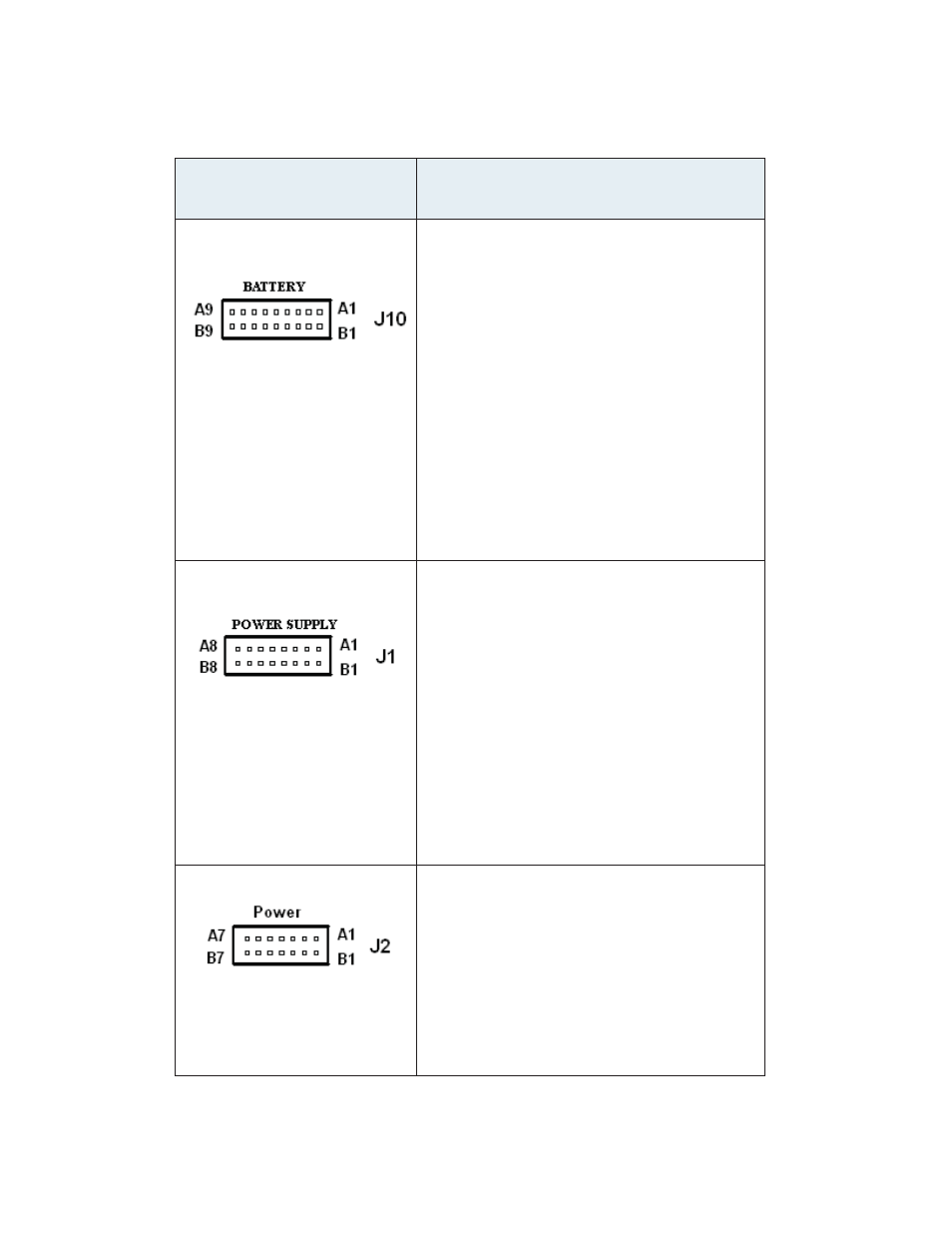
5.0 Transponder Connector Pinouts
Connector
Pinouts
Pins numbered right to left, facing front panel,
A = top row, B= bottom row
Battery Interface
A1 Battery 5+
A2 Battery 6+
A3 Battery 7+
A4 Battery 9+
A5 Battery 10+
A6 Battery 11+
A7 N/C
A8 N/C
A9 Chassis Ground
B1 N/C
B2 Battery V+
B3 Battery 3+
B4 Battery 2+
B5 Battery 1+
B6 Battery Reference V-
B7 Temperature Probe Power
B8 Temperature Probe Signal
B9 Temperature Probe Ground
Power Supply Interface (16 Pin)
Connector J1
A1 Charging Current
A2 Major Alarm
A3 Tamper
A4 Minor Alarm
A5 Inverter Status
A6 Output Current1
A7 Total Battery Voltage
A8 Output Current2
B1,B2 GND
B3 AC Input Voltage
B4 Inverter Control
B5 Spare Analog Input
B6 AC Power to the Transponder (Hot)
B7 AC Power to the Transponder (Neutral)
B8 Spare Input1
Power Supply Interface (14 Pin)
Connector J2
A1 Output Current1
A2 Output Current2
A3 Output Current3
A4 N/C
A5 N/C
B1-B5 GND
A6 Scaled AC Line Voltage Input
B6 GND
A7 AC to the Transponder (Hot)
B7 AC to the Transponder (Neutral)
Table 5-1, Transponder Connector Pinouts
- AlphaCell GelCell Series (32 pages)
- FXM 650, 1100, 2000 UPS (96 pages)
- Cordex 48-1.2kW (68 pages)
- Radium MiniBay (57 pages)
- Fiber Backhaul Enclosure (FBE) (19 pages)
- FBE2322 Enclosure System (38 pages)
- FlexNet PMR, GMR Series (49 pages)
- Te25xh (38 pages)
- FlexNet MPS48-12M - Technical Manual (33 pages)
- FlexNet MPS48-12M - Quick Start Guide (2 pages)
- FlexNet ELPM 300-48D (25 pages)
- FlexNet FMPS (40 pages)
- FlexPoint AX Series (34 pages)
- FlexPoint FPR1207-F - Technical Manual (18 pages)
- FlexPoint FPR1207-F - Quick Start Guide (2 pages)
- AlphaGen PN-6x-T 7.5kW 48VDC - Installation and Operation Manual (79 pages)
- AlphaGen CE-3x2 5K-T 48Vdc (95 pages)
- AlphaGen PN-6x-T 7.5kW 48Vdc (95 pages)
- AlphaGen 3.5_5.0kW Kohler COM5 (80 pages)
- Security Bar Field For UPE-3, UPE-6, UPE-M3, UPE-M6, PN Series and CE Series (2 pages)
- AMPS80 HP (116 pages)
- 255A Bypass Switch (24 pages)
- AMP24 HP (108 pages)
- FXM350_Micro350 UPS (112 pages)
- CFR 600, CFR 600XT, CFR 1000 (70 pages)
- BPS Series Bypass Switch (36 pages)
- CFR Intelligent Interface Device (54 pages)
- CFR Redundant Control Unit (23 pages)
- CFR 5000, CFR 5000RM (88 pages)
- CFR 3000, CFR 3000RM (86 pages)
- CFR 1500, CFR 1500RM (83 pages)
- CFR 1500, CFR 2000, CFR 2500, CFR 3000 (76 pages)
- Continuity: 1000_2000_3000 (48 pages)
- Continuity Battery Pack (20 pages)
- Continuity: 6K_10K (52 pages)
- Micro, Micro XL, Micro XL3 UPS (99 pages)
- Micro Secure UPS (80 pages)
- Te17 (32 pages)
- Te45 (68 pages)
- Te41, 48V (76 pages)
- Te41, 24V (72 pages)
- Te43 (60 pages)
- AlphaGuard AG-CMT Installation (2 pages)
- AlphaGuard AG-CMT-3SC_4SC-P (2 pages)
- Digital Midtron DM-3200 AT (2 pages)