Caution, Gro und – Alpha Technologies AlphaNet Series External DOCSIS User Manual
Page 28
28
745-838-B2-001 Rev. A
3.0
Installation Instructions for Specifi c Power Supplies, continued
3.4
Alpha/Lectro ZTT+ Series Power Supply, continued
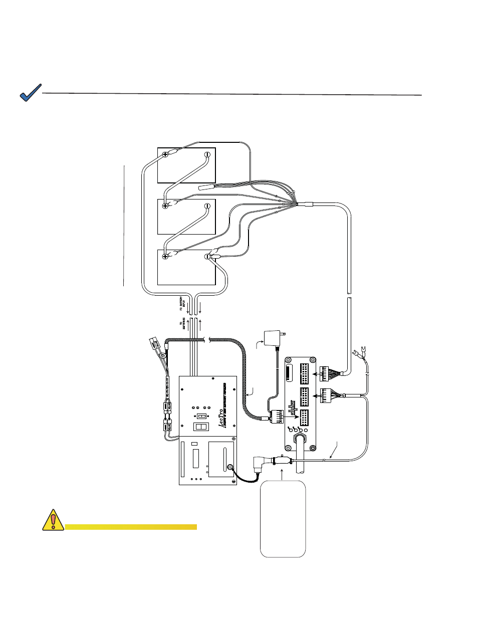
3.4.2 Connecting the Alpha/Lectro ZTT+ (Silver and Black)
US
T
AM
P
E
R
CBL-PS-INTFC-02-003
GRO
UND
PWR
INTERFACE CABLE
POWER SUPPLY
RF CABLE IN
SYSTEM
18 PIN
Power Supply
Power
DS
Ba
tter
y
GROUND
TAMPER
ONLINE
AC
FAULT / S
T
A
N
D
B
Y
V
A
NORMAL
AL
ERT
60
/9
0 VAC
ON
DC
OFF
B
A
TTER
Y
_
+
MU
LT
IPLE P
O
WE
R
IN
PU
TS
T
U
R
N
OF
F B
O
TH SW
ITCH
ES
T
O
F
U
LLY REMOVE
POWER
CABLE
AC
O
U
T
ZT
T /
Pl
u
s
36
VD
C
TO
LOAD
+
SLVR +BLK
ZTT
WIT
H
TRANSF
ORMER
9VAC
120VAC
TO
POWER OUT
P
UT CABLE
BLA
C
K
RE
D
+V
+2
4V
+
1
2
V
+3
6V
-V
BATT
TEMP
PROBE
PLACE
TEMP PROBE
BETWEEN
BATTERIES
BLA
C
K
RE
D
BATTERY CABLE
BATTERY 1
B
ATTERY 2
B
ATTERY 3
RE
D
BL
ACK
D
O
C
S
IS Tr
ansponder
AlphaNet
R
0A C4 36
BLACK RING DIN , ZTT+
MOVE THE SWITCH ON CABLE ASSY
TO THE " +BLK " POSITION
SILVER RING DIN , ZTT+
MOVE THE SWITCH ON CABLE ASSY
TO THE " +SLVR " POSITION
Fig. 3-11, Alpha/Lectro ZTT+ Series Silver and Black Installation
NOTE:
The Lectro ZTT+ installation diagram is the same for both the black and silver connector with the
exception of the switch setting on the interface harness. For a black connector, set the switch to the ZTT+
black position and for a silver connector, set the switch to the silver position.
CAUTION!
Improper wiring may damage the unit
and void the warranty.
Installation Note:
The + battery terminals face the front of the enclosure