Caution – Alpha Technologies AlphaNet Series External DOCSIS User Manual
Page 22
22
745-838-B2-001 Rev. A
3.0
Installation Instructions for Specifi c Power Supplies, continued
3.2
Alpha XM Series Power Supply, continued
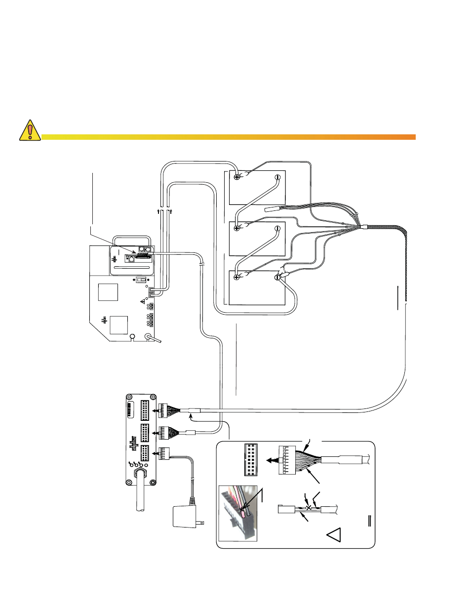
3.2.3 Connecting the XP-EDH-A2 to an XM Series Power Supply
Follow the diagram below to make all connections between the transponder and the
power supply site. The diagram is the cable installation guide drawing with interface,
three batteries, and power to an Alpha XM power supply.
RE
D
B
L
A
C
K
P
OWE
R S
U
P
P
LY
I
N
T
E
R
F
AC
E
P
o
w
e
r
Su
p
p
ly
P
W
R
Po
w
e
r
11
0V
A
C
Li
ne
I
n
p
u
t
PO
W
E
R
SU
P
P
L
Y
C
ABL
E
1
4
PI
N
R
F C
A
B
L
E
I
N
S
Y
ST
EM
US
DS
Ba
tt
er
y
18
P
IN
16
PI
N
C
BL
-P
S-BA
T
-0
4-
0
0
4
(4
FT
LO
N
G)
BA
T
T
E
RY
C
A
BL
E
PL
AC
E
TE
M
P P
RO
BE
BE
TW
E
EN
B
ATT
ER
IE
S
B
LA
C
K
B
A
TTE
R
Y
1
B
AT
T
TE
MP
PR
O
BE
-V
BA
TTE
R
Y
2
+1
2V
B
LA
C
K
+
24V
B
A
TTE
R
Y
3
+
V
RE
D
+3
6V
BA
T
T
ER
Y
S
T
R
ING
1
F
us
e
WA
R
N
IN
G
:
3
IND
IC
A
TO
R
L
AM
P
R
E
M
OT
E
ST
AT
US
R
E
L
A
Y
ST
AN
D
B
Y
1
2
O
UT
P
UT
4
6
5
A
C
BLAC
K
RE
D
BA
TTE
R
Y
C
O
N
N
E
C
T
OR
+
C
IR
C
UI
T
B
R
E
A
K
E
R
-
BA
TTE
R
Y
OF
F
Al
p
ha
S
E
R
I
E
S
Te
c
hn
ol
igi
es
X
M
B
LA
C
K
RE
D
WI
R
E
Y
E
L
L
OW
1
8
PI
N
Ba
tte
ry
Bl
ac
k
wir
e
Red/
G
re
e
n
wir
e
Vi
e
w
Si
d
e
Cu
t
Her
e
CUT A
ND RE
M
OVE
A
PI
E
CE
O
F
RE
D/
G
R
E
EN
W
IR
E I
F
PR
ESE
NT
F
O
R
X
M
SE
R
IES
O
N
L
Y
!
CU
T TH
E
W
IR
E
IN UP
P
E
R L
E
FT
P
O
S
IT
IO
N
A
S SH
O
W
N
. AN
Y W
IR
E
CO
L
O
R.
DO
CS
IS
Tr
a
n
spo
nd
e
r
A
lp
h
a
Ne
t
0A
C
4
3
6
ON
L
INE
Fig. 3-8, XM Series Installation with Three Batteries
CAUTION!
Improper wiring may damage the unit and void the warranty.
Installation Note:
The + battery terminals
face the front of the
enclosure
Important!
Plug in the 13 pin connector
so the black wire is in pin one
(the top pin) and two open
pins are left at the bottom for
tamper switch connection.