4 alpha/lectro ztt+ series power supply – Alpha Technologies AlphaNet Series External DOCSIS User Manual
Page 27
27
745-838-B2-001 Rev. A
3.0
Installation Instructions for Specifi c Power Supplies, continued
3.4 Alpha/Lectro ZTT+ Series Power Supply
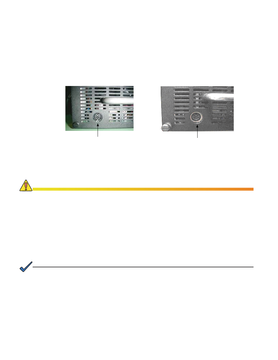
There are two models of the Lectro ZTT+ Series power supply inverter modules. You can
easily identify one type from the other by checking the round 6-pin DIN connector located on
the lower left side of the front panel:
Early units have a solid black DIN connector (pre-1998).
•
More current units have a silver band around the DIN connector.
•
Early (pre-1998) unit with solid black
connector
Current unit with silver band on connector
Fig. 3-10, Lectro ZTT+ Series Power Supplies
Procedures for installing the XP-EDH-A2 with both types of Lectro ZTT+ Series power
supplies follow and are differentiated by a silver or black designation.
3.4.1 Alpha/Lectro ZTT+ Installation (Silver and Black)
If commercial power is present at the site and the power supply is currently
1.
powered by commercial AC line voltage, turn the battery breaker OFF on the
power supply and disconnect the AC utility power.
Installing the XP-EDH-A2 transponder at Alpha/Lectro ZTT+, or ZTT sites requires temporarily disconnecting
the output of the power supply to the cable plant to insert one of the transponder harnesses in series with the
power supply output. This is necessary so the transponder can measure both the output voltage and output
current.
If a short power interruption is not feasible, you must use an alternate source of system power
during the
installation of the transponder
.
CAUTION!
Locate the transponder interface cable with the 6-pin type DIN connector. This
2.
harness has a selectable switch near the silver 6-pin shell. Place the switch in
the ZTT+ Silver position or in the Black position depending on what type of power
supply you are using.
Make all other harness connections following the diagram in Fig. 3-11.
3.
If a site tamper switch is employed, connect the two lugs within the harness to
4.
the connections on the door switch.
Restore AC utility power and place the DC breaker back to the ON position.
5.
NOTE:
Turning the battery breaker OFF disables the standby power supply.