1 xm series jumper settings, 2 output voltage calibration – Alpha Technologies AlphaNet Series External DOCSIS User Manual
Page 21
21
745-838-B2-001 Rev. A
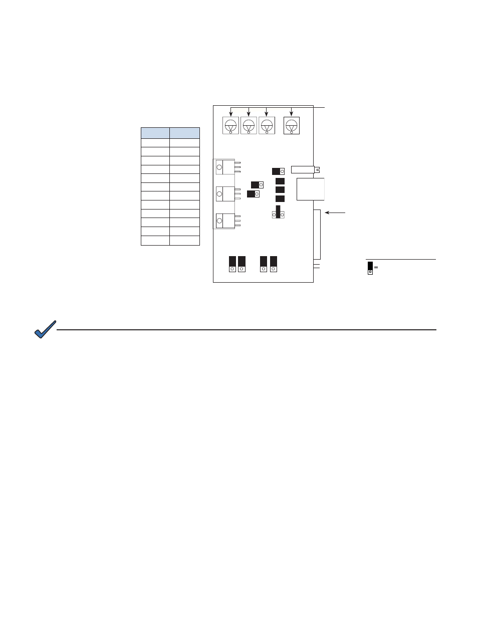
3.2.1 XM Series Jumper Settings
Fig. 3-7, XM/XP Power Supply Universal Status Monitor
(as viewed from rear of power supply with main control module partially removed)
Jumper
Position
P1
2-3
P2
open
P3
open
P4
closed
P5
closed
P6
closed
P7
5V
P8
1-2
P9
1-2
P13
1-2
P14
1-2
SW4
0
SW1
DC
1
2
3
Remove the USM and set
the jumpers as follow:
Set to 0
(SWs 1,2,3 may not be
present on some boards)
Potentiometer Adjuster
RJ Connector
Power Supply Interface
SW2
SW3
SW4
R8
1
2
1
2
1
2
1
1
1
P1
P2
P3
P4
P5
P6
P7
5V
24V 15V
P8
P9
P13 P14
AC
CUR
AC Volts
1
2
3
1
2
3
1
2
3
USM
3
PIN 1
Legend:
Pins jumpered
3.0
Installation Instructions for Specifi c Power Supplies, continued
3.2
Alpha XM Series Power Supply, continued
NOTE:
The switch settings in this section apply only to the EDH-A2 and differ from the EDH-A. Refer to the EDH-A
Installation Manual for EDH-A installation procedures.
3.2.2 Output Voltage Calibration
EDH-A2 supports AC Scaling for Output Voltage measurements and does not require
USM2.5 potentiometer calibration.
- AlphaCell GelCell Series (32 pages)
- FXM 650, 1100, 2000 UPS (96 pages)
- Cordex 48-1.2kW (68 pages)
- Radium MiniBay (57 pages)
- Fiber Backhaul Enclosure (FBE) (19 pages)
- FBE2322 Enclosure System (38 pages)
- FlexNet PMR, GMR Series (49 pages)
- Te25xh (38 pages)
- FlexNet MPS48-12M - Technical Manual (33 pages)
- FlexNet MPS48-12M - Quick Start Guide (2 pages)
- FlexNet ELPM 300-48D (25 pages)
- FlexNet FMPS (40 pages)
- FlexPoint AX Series (34 pages)
- FlexPoint FPR1207-F - Technical Manual (18 pages)
- FlexPoint FPR1207-F - Quick Start Guide (2 pages)
- AlphaGen PN-6x-T 7.5kW 48VDC - Installation and Operation Manual (79 pages)
- AlphaGen CE-3x2 5K-T 48Vdc (95 pages)
- AlphaGen PN-6x-T 7.5kW 48Vdc (95 pages)
- AlphaGen 3.5_5.0kW Kohler COM5 (80 pages)
- Security Bar Field For UPE-3, UPE-6, UPE-M3, UPE-M6, PN Series and CE Series (2 pages)
- AMPS80 HP (116 pages)
- 255A Bypass Switch (24 pages)
- AMP24 HP (108 pages)
- FXM350_Micro350 UPS (112 pages)
- CFR 600, CFR 600XT, CFR 1000 (70 pages)
- BPS Series Bypass Switch (36 pages)
- CFR Intelligent Interface Device (54 pages)
- CFR Redundant Control Unit (23 pages)
- CFR 5000, CFR 5000RM (88 pages)
- CFR 3000, CFR 3000RM (86 pages)
- CFR 1500, CFR 1500RM (83 pages)
- CFR 1500, CFR 2000, CFR 2500, CFR 3000 (76 pages)
- Continuity: 1000_2000_3000 (48 pages)
- Continuity Battery Pack (20 pages)
- Continuity: 6K_10K (52 pages)
- Micro, Micro XL, Micro XL3 UPS (99 pages)
- Micro Secure UPS (80 pages)
- Te17 (32 pages)
- Te45 (68 pages)
- Te41, 48V (76 pages)
- Te41, 24V (72 pages)
- Te43 (60 pages)
- AlphaGuard AG-CMT Installation (2 pages)
- AlphaGuard AG-CMT-3SC_4SC-P (2 pages)
- Digital Midtron DM-3200 AT (2 pages)