Installation, 5 component interconnection, 1 cable input wiring – Alpha Technologies FlexPoint AX Series User Manual
Page 24: 2 output cable wiring
24
010-318-C0-007, Rev. G
Input 12VDC
Output 12VDC
CNTRL
ALARM RETURN
AC F
AIL
REPLACE BA
TT
BA
TT
MISSING
BA
TTER
Y LOW
4.5 Component
Interconnection
Status
LEDs
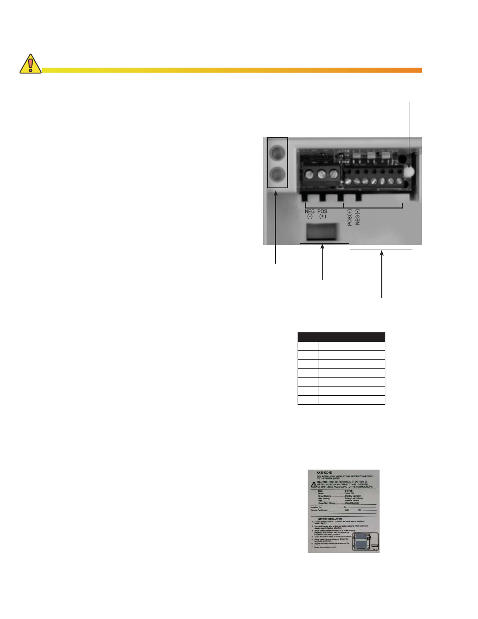
4.5.1 Cable Input Wiring
1. Ensure Power Ring Converter/Home
Converter is disconnected from AC
power, then strip all input wire ends
1/4".
2. Connect the input cable from the
Power-Ring/Home Converter into
the 3-pin "Input 12Vdc" plug in the
following order:
Pin 1, white (return)
Pin 2, black (12V)
Pin 3, green (control).
Tighten the plug screws with a
0.100" jeweler’s screwdriver.
4.5.2 Output Cable Wiring
1. Strip 1/4" from the output cable wire
ends.
2. Install wire ends in 7-wire connector
(Fig. 3-3), Tighten connector screws
with .100" jeweler's screwdriver.
3. Press connector onto "Output
12Vdc" header. The locator pin
prevents misalignment of the
connector. The connector pins are
labeled with their function. Refer
to the specifi c instructions from the
ONT supplier to determine what
alarms are accepted from the BBPS
to the ONT.
4. Connect the ONT cable according to
ONT manufacturer instructions.
5. Once the connections are complete,
the battery may be connected to
the system. The Green Status LED
should light indicating a charged
battery has been installed. Table 5-1
shows a complete list of LED Status
indications.
6. Secure the battery and replace the
battery module door.
Pin 1
Pin 1
Pin Function
1
POS (+)
2
NEG (-)
3
TEL COMM
4
AC FAIL
5
REPL BATT
6
BATT MISS
7
BATT LOW
Locator Pin
Input from
PRC or HC
Output to
NID/NIU/ONT
4. Installation
Fig. 4-3, Input/Output Connection Points
Table 4-1, Pin Out, Battery
Module 7-pin connector
Incorrectly connecting these wires will result in non-operation of the unit or cause equipment
damage.
CAUTION!
Fig. 4-4, Inner Label, AX-12D-BBPS-7.2