Installation – Alpha Technologies FlexPoint AX Series User Manual
Page 20
20
010-318-C0-007, Rev. G
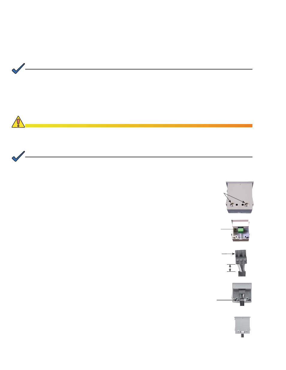
1. Loosen the two screws at the rear base of the Power-Ring Converter and
remove the cover plate from the front of the Power-Ring Converter.
2. Remove the keyed, 3-pin plug from the base of the converter.
3. Strip 1/4" from the cable wire ends. Minimize the gap between the outer
jacket of the cable and the end of the insulation for each individual wire.
Connect the cable from the Power-Ring into the 3-pin plug in the following
order:
Pin 1, white (return) [-], Pin 2, black (12V) [+], Pin 3, green (control) [c].
Tighten the plug screws with a 0.100" jeweler’s screwdriver. To reduce the
potential for a short circuit, verify no bare wire is showing, or loose strands
of wire are present between the cables.
4. Insert plug into socket. For strain relief, loop a cable tie through the holes
in the case and replace cover. Do not over-tighten screws.
Strain
Relief
Keyed plug
Loosen
Two options are available for powering either a battery module or subscriber’s NID/NIU/ONT: the
Power-Ring Converter (for power from the meter) and the Home Converter (plugs into a standard AC
utility outlet).
Prior to powering the converter, verify that the NIU/NID is properly grounded and connected to either
the 12V Lead (pin 2) of the battery module, or the Return Lead (pin 1) of the Power/Home Converter.
The FlexPoint AX does not make contact with Earth Ground through the meter socket; Earth Ground is
provided by connection to the NIU/NID. Prior to connection to the NIU/NID Earth Ground, the FlexPoint AX
output fl oats and may have enough leakage current to cause any one of the output leads to measure high
voltage with reference to Earth Ground. The energy represented by the high voltage does not represent a
safety hazard, but may cause a slight undesirable tingling sensation.
NOTE:
The converter can be installed at the same time as the Power-Ring, or at a later date. Refer to NOTE in
Section 2 on wire size and distance.
NOTE:
Improperly connecting these wires will result in equipment damage or non-operation of the unit.
CAUTION!
4. Installation
Pin 1
Minimize Gap
- + c
4.2
Installing the Power-Ring Converter