Installation for alarm wiring, Testing, Troubleshooting – Franklin Fueling Systems DC404-4 Controller User Manual
Page 6
6
Installation for Alarm Wiring
Important! For all applications, do not exceed the relay
contact rating of 250VAC, 12A.
The relay contacts (Orange / Black and Orange wires)
on the 404-4 controller are normally closed dry contacts
(when power to the controller is applied) that will open
when liquid is detected. This enables the DC400 to be
wired for various alarm notification and monitoring.
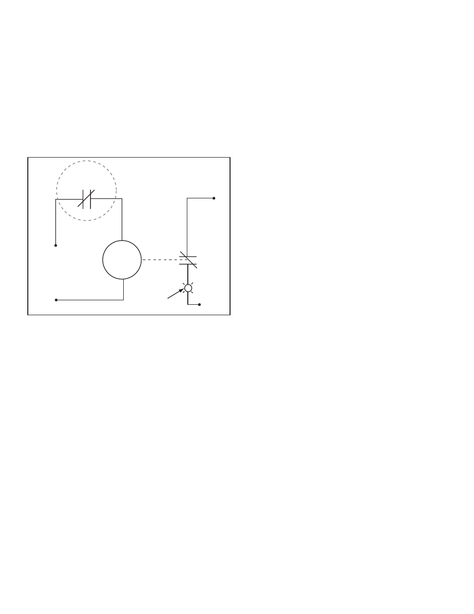
Figure 6 shows an example of alarm wiring for applications
that do not require positive shutdown but simply some sort
of visual and / or audible notification. In this example the
alarm light illuminates when the DC400 detects liquid.
120 VAC
120 VAC
Neutral
Neutral
404-4 Controller
Contacts
External
120 VAC
Relay Coil
N.C.
N.C.
120 VAC
Alarm Pilot Light
Orange / Blac
k
Orange
Figure 6: Wiring Example for Non-Positive Shutdown
Testing
Test the function of the system according to applicable
codes. Test immediately after installation, and at least
annually to verify proper system operation.
Troubleshooting
If the controller relay repeatedly cycles or oscillates
when the sensor is tripped, it is likely that the controller is
switching its own power. Check the wiring diagram and
confirm that the controller is wired properly. Make sure that
the orange / black, red and black wires are tied to power
from the breaker and the orange wire feeds the dispenser.
If problems continue, please contact FFS Technical
Support at 800-984-6266.