L1 l2 – Franklin Fueling Systems DC404-4 Controller User Manual
Page 5
5
3. Remove the STP junction box cover / plug. Make
sure the STP junction box has enough room to
accommodate the additional 404-4 controller wires
(see the table on page 2). Thread the six 404-
4 power wires from the power port through the
conduit fittings and plumb the conduit fittings to
the 404-4 controller. Connect the controller power
wires to the STP wiring as shown in figure 4.
Make sure to connect both ground
wires and verify they are connected
to earth ground. Failure to do so may
result in a fire or explosion hazard in
case of a fault condition.
4. Join the controller conduit to the STP junction
box cover and replace the cover on the STP
and securely tighten. A union will be required to
do this, (see Figure 3). A conduit seal must be
installed between the electrical junction box and the
controller. The conduit seal must be within 18” of
the electrical junction box and the 404-4 controller.
Multiple conduit seals may be required for some
installations, depending upon the ditance between
the electrical junction box and the 404-4 controller.
Refer to NEC NFPA 70, article 501.15 (A) (3), 2011.
5. Connect the sensor wire cable coming from
the 404-4 controller to the appropriate Franklin
Fueling Systems sensor. Reference the sensors
installation instructions for installation, wiring and
testing of the sensor.
6. Turn the STP circuit breaker back on and test
the DC400 system for proper operation. With the
sensor dry, the STP should operate normally.
7. Next, test the DC400 pump cutoff by submerging
the sensor in water. The pump should shut off and
remain off as long as the sensor is submerged.
(Note: if the pump is controlled and monitored by
an external pump controller or tank gauge, this
device may need to be reset when the sensor is
removed from the water).
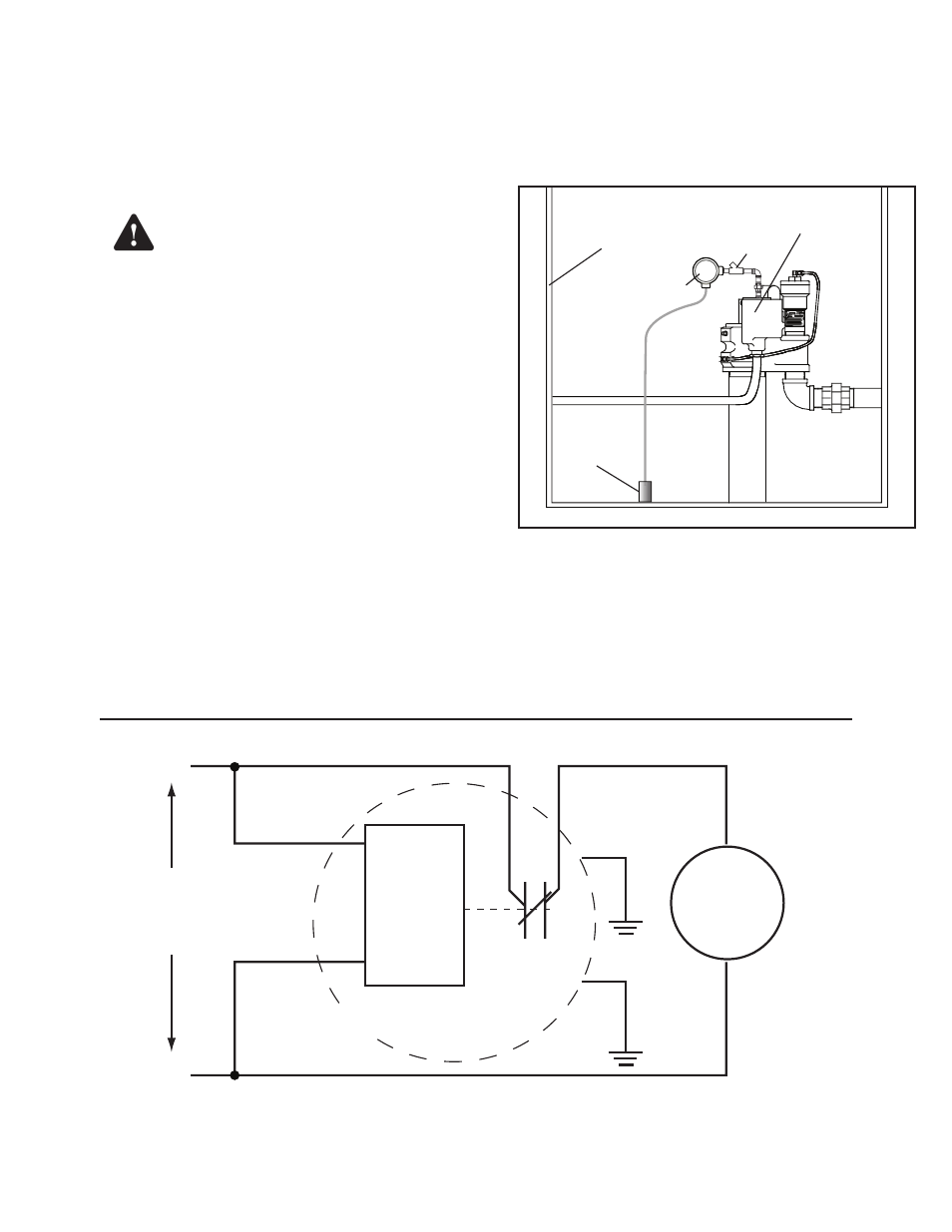
404-4 Controller
STP Electrical
Junction Box
2-Wire or
3-Wire Sensor
STP Sump
EYS
Figure 5: Typical STP Sump Installation
Controller
/Relay
STP
Black
Black
Orange / Black
Orange
White
N.C.
(When Dry)
From pump
control relay
or contactor
(220 VAC)
L1
L2
* Ye
llow/Green
Green
404-4 Controller
* Safety Ground
Figure 4: Power Wiring Schematic for STP Connection
Warning