Pvt series • connections and settings 12 – Extron Electronics PVT Series User Guide User Manual
Page 18
Ö
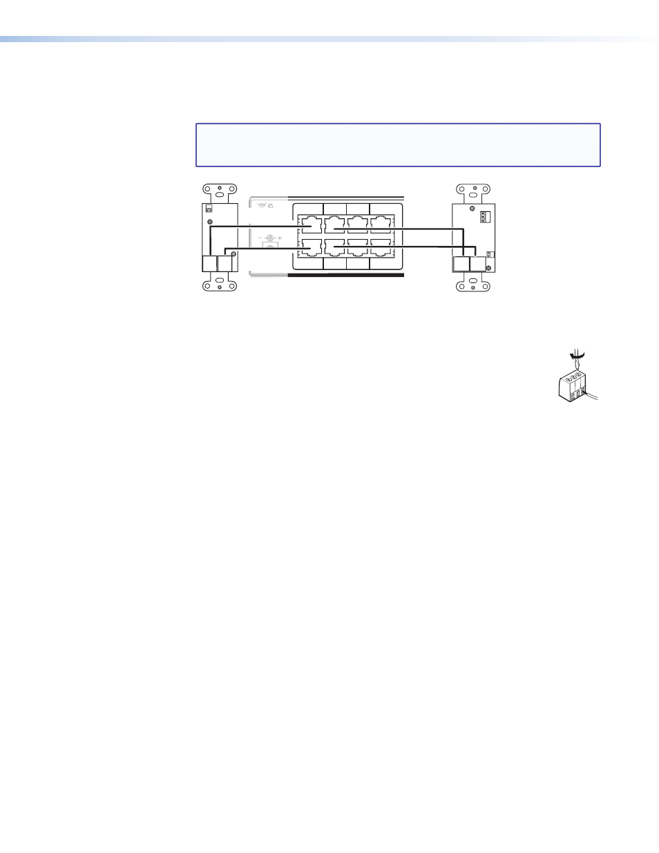
RGB B output (PVT RGB models) — Using CAT 5e or 6 UTP cable, connect this RJ-45
female output port labelled “RGB A out” to one of the input ports labelled B (for
example, 2B) on the PoleVault switcher.
NOTE: Cable A carries horizontal sync information and the red, green, and
blue signals. Cable B primarily carries the audio signal, the vertical sync
information, and 5 VDC to power the PVT transmitter.
G S
RGB A
OUT
RGB B
OUT
G R L
RGB A
OUT
RGB B
OUT
G S
1B RGB
1A RGB
2B RGB
2A RGB
3B RGB
/VIDEO
4B RGB
/VIDEO
3A RGB
4A RGB
I
N
P
U
T
S
POWER
N15779
12V
5A MAX
POWER
N1577
12V
5A MAX
7
PVT RGB D
Input #1
RGB Input Connectors on
the Rear Panel of the
PVS Switcher
Cable from
PVT Output B
Rear Panel
Rear Panel
PVT RGB D PLUS
Input #2
Cable from
PVT Output A
Cable from
PVT Output B
Cable from
PVT Output A
Figure 15.
Connecting the PVT RGB D or PVT RGB D Plus to the PoleVault
switcher
d
Audio pass-through connector (PVT RGB D Plus models) — Connect an
audio source to this 3-pole connector for audo pass through output. Connect
the ground to “G”, right speaker to “R”, and left speaker to “L”.
e
EDID Minder 5-pole DIP switch — If the display refresh rate and resolution
is known, set the EDID Minder 5-pole DIP switches according to the EDID table
(see “
” section, page 13 for details).
Alternatively, if the EDID Minder is used in Learn mode, set all the DIP switches to off.
G
L
R
PVT Series • Connections and Settings
12