Running cables, Installing cable retractors (optional), Installing the power modules – Extron Electronics TLP 710CV User Guide User Manual
Page 14: Run but do not connect the cables, Install cable retractors, Install the power module, Installing cable retractors, Installing power modules
Running Cables
Run all cables necessary to support the AC connector, the cables stored in the cubby, and all
planned AAP connectors. Run the cables below the table and through the hole that was cut
in the previous step (“
”). Leave enough slack in the cables to connect or
route them before the cubby is installed in the table. Leave enough slack for the external power
supply and to connect AV cables and the cable for PoE and LAN to the TLP 710CV.
Installing Cable Retractors (Optional)
Extron cable retractors retract and store extended cables in Cable Cubby systems, preventing
them from tangling underneath the table. Retractor kits are available for several cable types.
Up to six retractors can be installed in the TLP 710CV enclosure (three on either end). They are
not provided with the TLP 710CV and must be purchased separately.
The buttons on the retractors must be placed at one end of the unit and must, therefore, be
the first or the last items added. For complete information and installation instructions, see the
Retractors User Guide, which is available from the Extron web site (
www.extron.com
).
Installing the Power Modules
WARNINGS: • Switch off all electrical power before connecting the AC conduit to a
junction box, and keep power off until installation is complete.
• If the power cable is installed next to the retractors, ensure the power
cable cannot get tangled in the cable retractor mechanism.
CAUTION: All electrical installation must be performed by qualified personnel in
accordance with local and national electrical codes.
NOTE: Different countries require different power adapters. For models that do not
include a power module, see the Extron website to select a power module that is
suitable for your location.
The power module takes up two or three AAP spaces and may be installed before or after the
AAP assembly is installed or, if desired, with AAPs on either side.
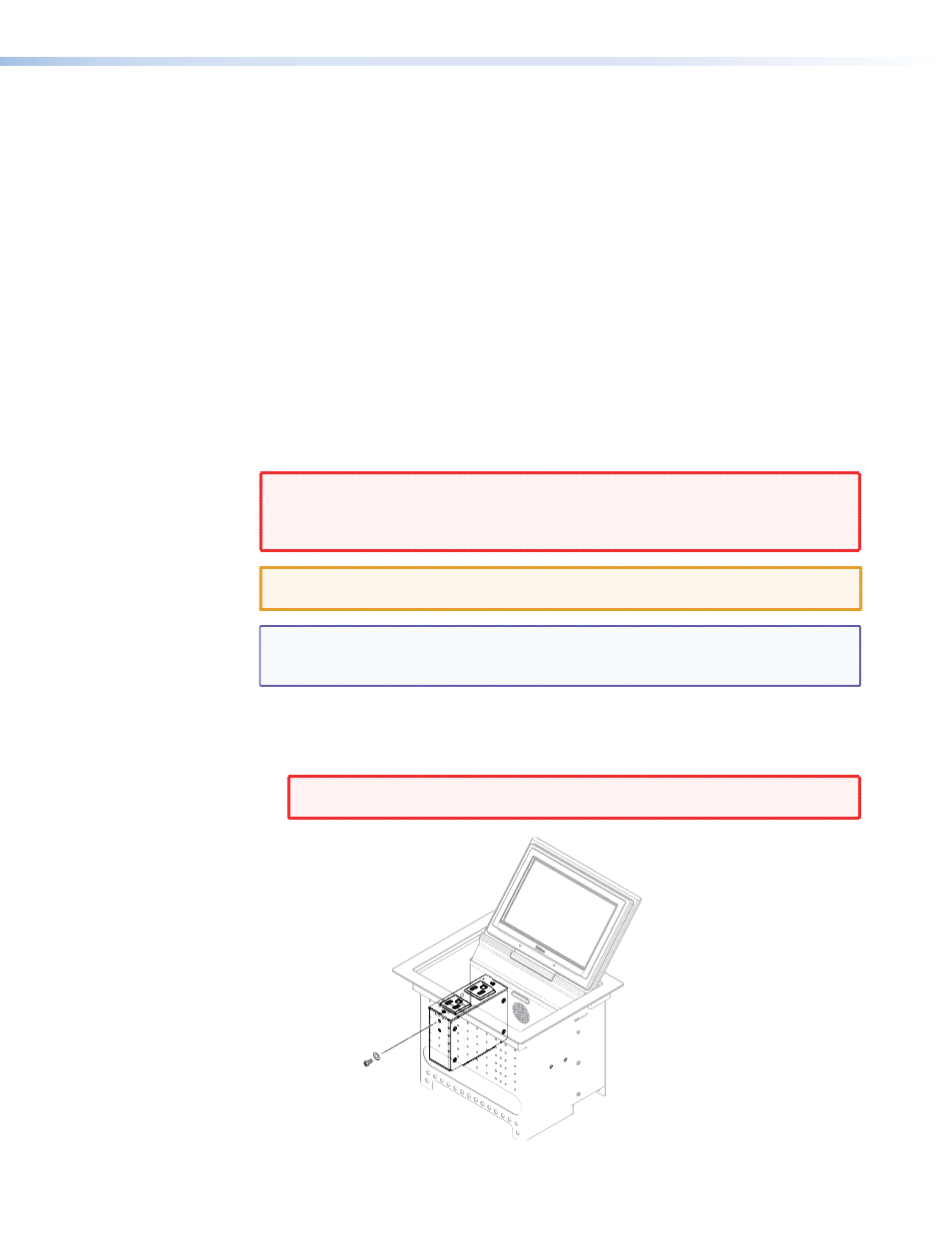
1.
Secure the power module into position with #4-40 Phillips head screws and star washers.
WARNINGS: To ensure good electrical grounding, you must use the star washers with
the screws.
Secure the power module
to the TLP 710CV frame
with #4-40 Phillips head
screws and star washers.
Figure 2.
Installing the power modules
TLP 710CV • Mounting
8