Installation and connection, cont’d, Menu next – Extron Electronics MKP 1200 Keypad User Manual
Page 9
MKP 1000/1200 • Installation and Connection
MKP 1000/1200 • Installation and Connection
Installation and Connection, cont’d
2-5
2-4
Next to the 3.5 mm connectors on the back of the MKP keypad there is a
label marking pins A through E. When using the recommended cable,
assign the colors according to figures 2-2 and 2-3. If you are making the
cables, see page 2-6 for details.
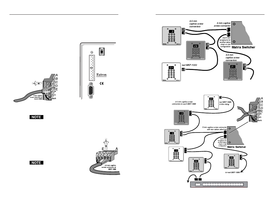
Connecting to a Matrix 3200/6400/12800
The two 5 mm connectors on the rear
panel of the 3200/6400/12800 master unit
(address 0) are also labeled A through E.
The cable connections must be made
such that A on the MKP keypad goes to
A on the 3200/6400/12800 connector, B
to B, etc. See Figure 2-3.
Figure 2-3 — The 5 mm connectors are on the rear of
the 3200/6400/12800
If the cables are not already made and installed, refer to
“Making Cables” on page 2-7. If the cables are already
made, connect them as shown in the diagrams that follow.
Connecting to a 3200/6400/12800 in a Daisy Chain
Configuration
The cables can be connected from one MKP keypad to
another in a daisy-chain fashion. Therefore either cable
may be plugged into either of the two 3.5 mm
connectors on the MKP circuit board shown in figure
2-2.
The orientation for the connectors
is with the black wire to pin #1.
See the detailed information on
the next page.
Figure 2-4 — Cable connections to the MKP Circuit
Board
As many as 64 MKP keypads may be connected using this method. The
total, maximum cable length is 1,000 feet – whether using daisy chain,
star, or combination configuration.
MKP COMM.
RS232/RS422
A
B
C
D
E
A
B
C
D
E
ADDRESS
ANAHEIM, CA
MADE IN USA
4
-
+
Figure 2-5 — MKP keypads connected in a daisy
chain configuration
Figure 2-6 — MKP keypads connected in a star/daisy
chain configuration
1
MCP 1000
MENU
NEXT
next
Note: MCP 1000 panels may be mixed with MKP 1000s.