Chapter three – Extron Electronics MKP 1200 Keypad User Manual
Page 11
MKP 1000/1200 • Installation and Connection
Installation and Connection, cont’d
MKP 1000/1200
3
Chapter Three
Operating the MKP Keypads
Programming the MKP 1000
Using the MKP 1000
Programming the MKP 1200
Using the MKP 1200
MKP Keypad Status on the FPC 1000
2-8
The total cable length for MKP keypads in a Matrix
system (up to 64) should not exceed 1,000 feet (305 m).
1.
Trim approximately 1.5 inches of the cable jacket to expose
the four insulated wires and a bare drain wire (silver-
colored).
2.
Cut off the foil shield and discard it.
3.
Strip 1/4” of insulation from each of the
four wires.
4.
Twist the strands of the black wire,
insert it into the opening that
corresponds with pin #1 on the circuit
board and tighten its captive screw.
5.
Twist the strands of the drain wire,
insert it into position #2 (D) and
tighten its screw.
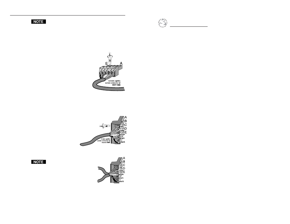
Figure 2-9 — Inserting wires into
a 3.5 mm captive screw connector (#10-319-10)
6.
Connect the remaining wires the same way (white, violet
& red).
7a.
If the cable is going to another MKP keypad, repeat steps
1-6 for the 3.5 mm connector on the other
end.
7b.
If the cable is going between an MKP
keypad and the 3200/6400 master
BME, use the same procedure with
the 5 mm captive screw
connector as shown in
Figure 2-10.
Figure 2-10 — Inserting wires into a 5 mm captive
screw connector (#10-163-13)
Cable wire assignments must be the
same on both ends or damage may
occur to circuits in the keypads.
Figure 2-11 — Inserting two sets of
wires into a 5 mm connector
1