Extron Electronics MKP 1200 Keypad User Manual
Page 10
MKP 1000/1200 • Installation and Connection
MKP 1000/1200 • Installation and Connection
Installation and Connection, cont’d
2-6
2-7
Connecting to a 3200/6400/12800 in a Star Configuration
The MCP 1000 switcher uses a 5 mm captive screw connector. The larger
holes can accommodate more than one set of wires, allowing up to three
cables to be inserted into each connector for making “star” connections
(see figure 2-6).
There is no termination required for the last MKP
keypad.
Connecting Through an MCP 1000 Master (including
Matrix 12800)
Since the keypad can only be directly connected to matrix switchers
which have the proper 5 mm connectors, the MCP 1000M (master)
remote control panel may be used to indirectly connect the keypad to a
switcher with an MKP Comm-Link port. The MCP 1000 master can be
connected to a matrix switcher through the RS-232 ports. The keypad
may then be connected to the MCP through the 5 mm Comm-Link port of
the MCP 1000. See figure 2-7 and refer to the MCP 1000 User’s Manual for
further details.
Figure 2-7 — MKP 1000s connected
through an MCP 1000M (master)
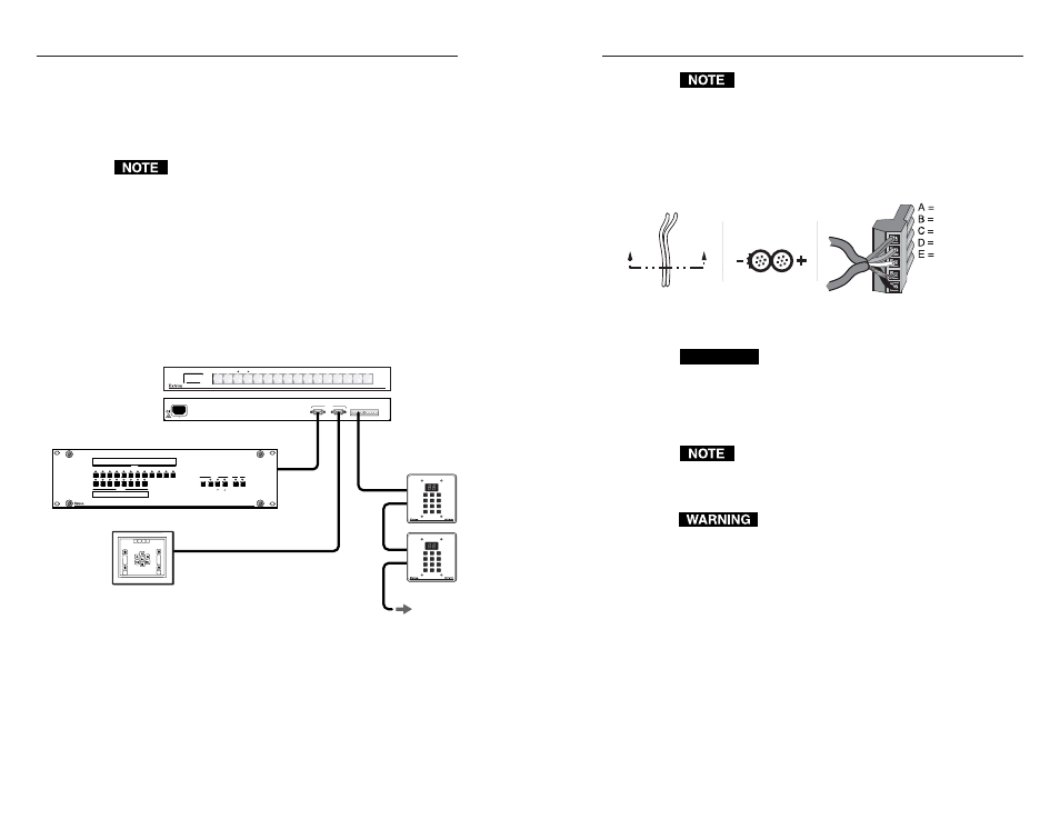
Connecting a Local Power Supply (MKP 1200 only)
When more than 24 MKP 1200s are connected, or the control cable is 300’
or more, local power may be required to support additional units. Error
Code E99 displayed intermittantly on an MKP 1200 panel may also
indicate the need for external power. The required power supplies are
available from Extron (part #70-055-01) as needed. Refer to figure 2-8,
and the following notes, for information on how to wire a power supply
into the 5-pole, captive screw connectors used to link the units.
When an external power supply is used, the A and B
(+12V) connections must be removed at the Matrix
12800 to isolate the group of keypads using the external
power, prior to connecting the power supply. If more
than one external power supply is required (>24
keypads), each group of keypads using a power supply
must be isolated from the others by removing the A and
B (+12V) connections between the groups.
Figure 2-8 — Power connector wiring (MKP 1200
only)
CAUTION
When connecting the power supply, voltage
polarity is extremely important. Applying power
with incorrect voltage polarity could damage the
power supply and the keypad. Identify the power
cord negative lead by the ridges on the side of the
cord.
Do not tin the stripped power supply leads before
installing the captive screw connector. Tinned wires are
not as secure in the captive screw connectors and could
pull out.
The two power cord wires must be kept separate
while the power supply is plugged in. Remove
power before continuing.
To verify the polarity before connection, plug in the power supply with
no load and check the output with a voltmeter.
Making Cables
Choose a cable such as Extron’s Comm-Link cable, AMX’s Axlink, or
Crestron’s Crestnet. The wire specifications for Comm-Link cable are on
page A-7. Colors may vary from this example.
Each MKP keypad ships with two 3.5 mm, 5-pole captive screw
connectors. The Matrix 3200/6400/12800 switchers ship with two 5 mm,
5-pole connectors. Cables that go from one MKP keypad to another
(daisy-chain) use the a 3.5 mm connector on each end.
MCP 1000 (master)
CrossPoint Plus or Matrix 12800
MKP 1000
RS-232
RS-232
Comm-Link
Up to 64
MKP 1000s
E
D
COMM - LINK PORT
RS-232
1.5A MAX.
100-240V 50/60Hz
HOST
SWITCHER
C B A
E
D C B A
Third Party Controller
1
1
2
2
3
3
4
4
5
5
6
INPUTS
ENTER
OUTPUTS
6
7
7
8
9
10
11
PRESET
VIEW
ESC
RGBHV
AUDIO
12
8
CONTROL
IO
CROSSPOINT PLUS SERIES SWITCHER with DSVP
VIEW
ENTER
0
1
2
3
4
5
6
7
8
9
VIEW
ENTER
0
1
2
3
4
5
6
7
8
9
MCP 1000
MENU
NEXT
1 2
3
4 5
6
7 8
9 10
AUD.VID.
SWITCHER
Power Supply +12V
Power Supply - Gnd
Power Supply +12V
Power Supply - Gnd
Communications
Power Supply Output cord
End view of power
supply output cord
A
A
SECTION A–A