Extron Electronics MLA VC10 Plus User Guide User Manual
Page 16
3.
Ensure you know the maximum control voltage for your amplifier. In this example, the
maximum voltage output range for the amplifier is 10 VDC.
For more information, see the user guide for the amplifier or measure the voltage, as
described in the previous section.
4.
If necessary, use an SIS command to set maximum voltage
output. For example, to set the maximum voltage to 7.5 V:
E
V*7.50VLCM
}
5.
Disconnect the USB connection to the computer.
6.
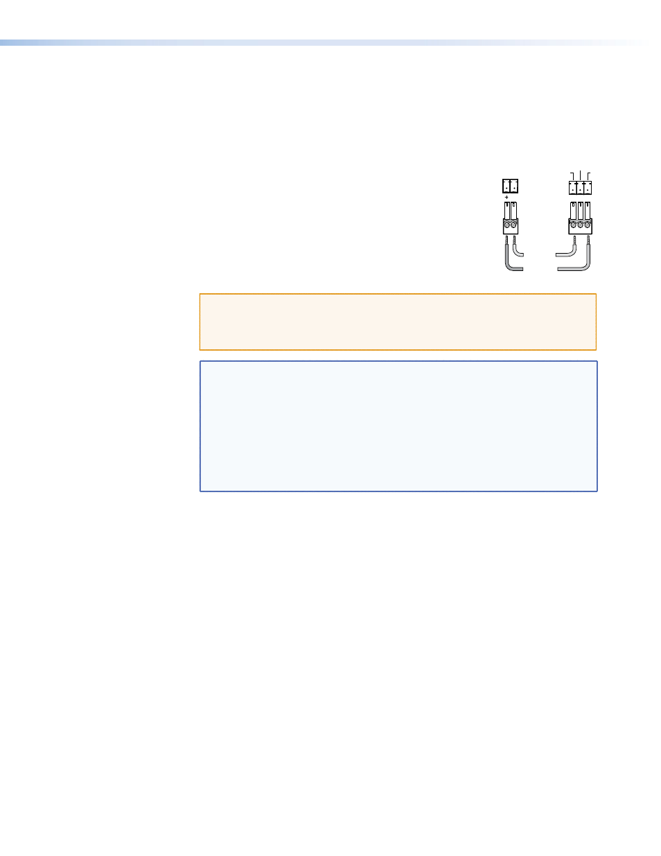
Connect the MLA VC10 Plus Voltage pins to the amplifier:
z
Connect the ground (G) terminal of the MLA VC10 Plus to
the ground (GND) terminal of the amplifier.
z
Connect the control signal voltage (+) terminal of the
MLA VC10 Plus to the control signal voltage (Vc) terminal
of the amplifier.
ATTENTION: There is some variation in how manufacturers mark control
terminals. To ensure that connections between the volume control
module and the amplifier are wired correctly, see the user guide for
that device.
NOTES:
•
See the
for important information about connecting
wires to captive screw connectors.
•
The cable between the MLA VC10 Plus and the amplifier should not be
more than 6 feet (1.8 m). Longer cables can pick up background noise
that affects sound quality.
•
In some applications the front panel volume control knob of the
amplifier may be disabled when the MLA VC10 Plus is attached to the
control port of the amplifier. In those cases the volume can only be
controlled by the MLA.
GND
Vc
+10V
+ to Vc
G to GND
Extron
MLA VC10 Plus
V-DC
G
Amplifier
MLA VC10 Plus • Installation and Cabling
10